
Page 226 - Renewable Energy Devices and System with Simulations in MATLAB and ANSYS
P. 226
Electric Generators and their Control for Large Wind Turbines 213
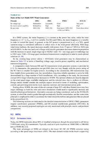
TABLE 9.2
State-of-the-Art Multi-MW Wind Generators
Principle DFIG CRIG PMSG DCE-SG
By voltage sags Medium/low Acceptable Good Very good
By reactive power capability Medium/low High High High
By gear ratio 100/1 (3G) 100/1 (3G) None (up to 5 MW) 50/1 None (direct drive)
(1/2G) (at 8 MVA)
In a DFIG system, the stator frequency f is constant at the power line value, while the rotor
1
frequency f = S * f (S max = ±0.3) is variable. For SGs and CRIGs, the stator frequency f is variable
1
2
1
3
in order to control the speed. In general, as the WT power is proportional to ω , a ± 30%, speed
r
variation range is considered sufficient to collect most of the wind power efficiently. With large
wind-tower turbines, the speed decreases steadily with power, from 15 rpm at 3 MVA to 10(9) rpm
at 8(10) MVA. As the size (and cost) of large wind electric generators decreases almost in proportion
with the increase in speed, single-stage (up to 10[20]/1 ratio: 1G—one stage gear) or multistage (up
to 250/1 ratio: 3/4G—3/4 stage gear) mechanical transmission is employed in order to reach optimal
solutions [9, 10].
So far, existing large power (above 1 MVA/unit) wind generators may be characterized as
shown in Table 9.2 in terms of handling voltage sags, reactive power capability, and mechanical
transmission/gearing.
A comparative study between DD and 3G transmission wind generator systems is provided in
[11]. To summarize, the generation cost per kWh does not vary sharply with the power rating of
the WT but it is smaller for higher powers. According to the calculations, DD transmissions may
have slightly lower generation cost, but, nevertheless, long-time reliable operation is yet to be fully
demonstrated by a large number of field installations. Also, according to the study, the investment
cost per kW is larger when the power increases to 10 MW. The optimal solution also heavily depends
on the wind speed range, available wind power, and the selected sites, that is, onshore or offshore.
Design studies should consider the multiple aspects involved in terms of modeling, optimization,
control, and grid integration in the local, regional, national, and international power grids.
Scaling above 10 MW, the state-of-the-art concept of large WT with three bladed rotors may face
major challenge as both the rotor and tower dimensions would need to significantly increase and
stretch technological limitations. Alternative concepts are being considered, such as the INVELOX
system, in which the wind is guided through mechanically flexible towers/tubes, and the vortex tube
principle is employed in order to accelerate the wind toward the turbine and generator that are placed
at the ground level [5].
The following sections are dedicated to the detailed characterization of DFIG, CRIG, permanent
magnet synchronous generator (PMSG), and DC-excited synchronous generator (DCE-SG). In
addition, very recently proposed topologies are only mentioned with principle, merits, and pertinent
comparisons.
9.2 DFIG
9.2.1 Introduction
Today, the DFIG represents about 50% of installed wind power, though the power/unit is still below
5 MVA/unit using 3G transmission. Typically used are 6-pole machines at 1000(1200) ± 300(400)
rpm at 50(60) Hz [12].
The main advantages of DFIG are related to the lower AC–DC–AC PWM converter rating
according to the speed range (maximum ±30%). The main demerit resides in the brush–copper ring