
Page 338 - Renewable Energy Devices and System with Simulations in MATLAB and ANSYS
P. 338
Batteries and Ultracapacitors for Electric Power Systems with Renewable Energy Sources 325
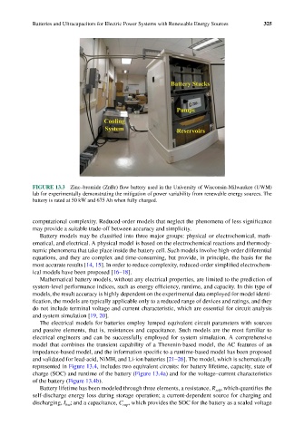
FIGURE 13.3 Zinc–bromide (ZnBr) flow battery used in the University of Wisconsin-Milwaukee (UWM)
lab for experimentally demonstrating the mitigation of power variability from renewable energy sources. The
battery is rated at 50 kW and 675 Ah when fully charged.
computational complexity. Reduced-order models that neglect the phenomena of less significance
may provide a suitable trade-off between accuracy and simplicity.
Battery models may be classified into three major groups: physical or electrochemical, math-
ematical, and electrical. A physical model is based on the electrochemical reactions and thermody-
namic phenomena that take place inside the battery cell. Such models involve high-order differential
equations, and they are complex and time-consuming, but provide, in principle, the basis for the
most accurate results [14, 15]. In order to reduce complexity, reduced-order simplified electrochem-
ical models have been proposed [16–18].
Mathematical battery models, without any electrical properties, are limited to the prediction of
system-level performance indices, such as energy efficiency, runtime, and capacity. In this type of
models, the result accuracy is highly dependent on the experimental data employed for model identi-
fication, the models are typically applicable only to a reduced range of devices and ratings, and they
do not include terminal voltage and current characteristic, which are essential for circuit analysis
and system simulation [19, 20].
The electrical models for batteries employ lumped equivalent circuit parameters with sources
and passive elements, that is, resistances and capacitance. Such models are the most familiar to
electrical engineers and can be successfully employed for system simulation. A comprehensive
model that combines the transient capability of a Thevenin-based model, the AC features of an
impedance-based model, and the information specific to a runtime-based model has been proposed
and validated for lead-acid, NiMH, and Li-ion batteries [21–26]. The model, which is schematically
represented in Figure 13.4, includes two equivalent circuits: for battery lifetime, capacity, state of
charge (SOC) and runtime of the battery (Figure 13.4a) and for the voltage–current characteristics
of the battery (Figure 13.4b).
Battery lifetime has been modeled through three elements, a resistance, R , which quantifies the
self
self-discharge energy loss during storage operation; a current-dependent source for charging and
discharging, I ; and a capacitance, C , which provides the SOC for the battery as a scaled voltage
cap
bat