
Page 339 - Renewable Energy Devices and System with Simulations in MATLAB and ANSYS
P. 339
326 Renewable Energy Devices and Systems with Simulations in MATLAB and ANSYS ®
®
Battery lifetime V–I characteristics
model model
R (SOC) R 1 (SOC) R (SOC) R (SOC)
2
S
3
+ +
3
2
R self C cap V SOC Voc(SOC) + C 1 (SOC) C (SOC) C (SOC) V t
–
I batt
– I batt –
(a) (b)
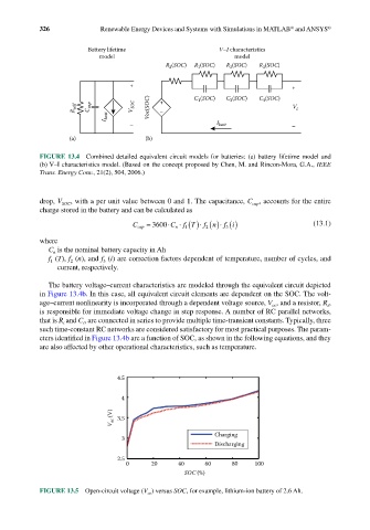
FIGURE 13.4 Combined detailed equivalent circuit models for batteries: (a) battery lifetime model and
(b) V–I characteristics model. (Based on the concept proposed by Chen, M. and Rincon-Mora, G.A., IEEE
Trans. Energy Conv., 21(2), 504, 2006.)
drop, V SOC , with a per unit value between 0 and 1. The capacitance, C , accounts for the entire
cap
charge stored in the battery and can be calculated as
fn
fT
C cap = 3600 ⋅ C n ⋅ ()⋅ ()⋅ () i (13.1)
1
f 3
2
where
C is the nominal battery capacity in Ah
n
f (T), f (n), and f (i) are correction factors dependent of temperature, number of cycles, and
2
1
3
current, respectively.
The battery voltage–current characteristics are modeled through the equivalent circuit depicted
in Figure 13.4b. In this case, all equivalent circuit elements are dependent on the SOC. The volt-
age–current nonlinearity is incorporated through a dependent voltage source, V , and a resistor, R ,
s
oc
is responsible for immediate voltage change in step response. A number of RC parallel networks,
that is R and C , are connected in series to provide multiple time-transient constants. Typically, three
i
i
such time-constant RC networks are considered satisfactory for most practical purposes. The param-
eters identified in Figure 13.4b are a function of SOC, as shown in the following equations, and they
are also affected by other operational characteristics, such as temperature.
4.5
4
V oc (V) 3.5
Charging
3
Discharging
2.5
0 20 40 60 80 100
SOC (%)
FIGURE 13.5 Open-circuit voltage (V oc ) versus SOC, for example, lithium-ion battery of 2.6 Ah.