
Page 343 - Renewable Energy Devices and System with Simulations in MATLAB and ANSYS
P. 343
330 Renewable Energy Devices and Systems with Simulations in MATLAB and ANSYS ®
®
13.4 ENERGY STORAGE MANAGEMENT SYSTEMS (ESMS)
13.4.1 Main Concepts
An ESMS is typically employed in order to ensure optimal and safe operation of devices, such as
batteries and ultracapacitors. A typical ESMS configuration includes an effective cell balancing
mechanism; cooling and ventilation; data acquisition and controls; communications and interfaces
between subsystems and with the power system; protections; for example, to overvoltage and short
circuit; condition monitoring for SOC and state of health (SOH); and temperature.
The management systems for both batteries and ultracapacitors share the same basic principles,
but batteries require additional care as their lifetime and safe performance are highly sensitive to
parameters like high temperatures, DOD, and current rate. Consequently, the focus in this section
is on battery management systems (BMS) and includes topics related to the SOC, SOH, and state
of life (SOL).
In terms of functionality, BMSs may be divided into three categories: centralized, modular or
master–slave, and distributed. In a centralized BMS, parameters such as voltage, current, and tem-
perature are measured for individual cells and sent to the main BMS board. This topology is com-
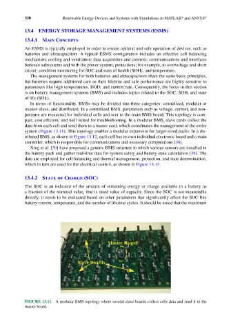
pact, cost efficient, and well suited for troubleshooting. In a modular BMS, slave cards collect the
data from each cell and send them to a master card, which coordinates the management of the entire
system (Figure 13.11). This topology enables a modular expansion for larger-sized packs. In a dis-
tributed BMS, as shown in Figure 13.12, each cell has its own individual electronic board and a main
controller, which is responsible for communications and necessary computations [38].
Xing et al. [39] have proposed a generic BMS structure in which various sensors are installed in
the battery pack and gather real-time data for system safety and battery state calculation [39]. The
data are employed for cell balancing and thermal management, protection, and state determination,
which in turn are used for the electrical control, as shown in Figure 13.13.
13.4.2 State of Charge (SOC)
The SOC is an indicator of the amount of remaining energy or charge available in a battery as
a fraction of the nominal value, that is rated value of capacity. Since the SOC is not measurable
directly, it needs to be evaluated based on other parameters that significantly affect the SOC like
battery current, temperature, and the number of lifetime cycles. It should be noted that the maximum
FIGURE 13.11 A modular BMS topology where several slave boards collect cells data and send it to the
master board.