
Page 348 - Renewable Energy Devices and System with Simulations in MATLAB and ANSYS
P. 348
Batteries and Ultracapacitors for Electric Power Systems with Renewable Energy Sources 335
L DC
+
AC L
Energy
C DC V DC storage
C
–
(a)
L DC
+
AC L
Energy
C DC V DC storage
C
–
(b) n
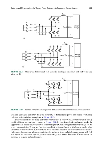
FIGURE 13.16 Three-phase bidirectional buck converter topologies: six-switch with IGBTs (a) and
a four-leg (b).
L DC
+
AC L
C DC V DC Energy
storage
C
–
FIGURE 13.17 A matrix converter that can perform the function of a bidirectional buck–boost converter.
Cuk and Sepic/Luo converters have the capability of bidirectional power conversion by utilizing
only two active switches, as depicted in Figure 13.19.
The circuit schematic for a HB converter, which is also a bidirectional power converter widely
used in different applications, is shown in Figure 13.20. In step-down, buck, or charging mode, the
upper switch is on and the power flow is from the higher DC link voltage to the lower voltage for the
energy storage device. The power flow is reversed in the step-up, boost, or discharging mode, when
the lower switch conducts. HB converters use a smaller number of passive elements and smaller
inductors and experience a lower current stress for active switches and diodes as compared with Cuk
and Sepic/Luo converters operating at the same voltage and power. Therefore, HB converters are
expected to achieve higher efficiency.