Page 349 - Renewable Energy Devices and System with Simulations in MATLAB and ANSYS
P. 349

336             Renewable Energy Devices and Systems with Simulations in MATLAB  and ANSYS ®
                                                                                ®


                                                                     +
                                                                   C DC
                          AC    L
                                                                      V DC  Energy
                                                                          storage

                                                                   C DC
                                                                     –


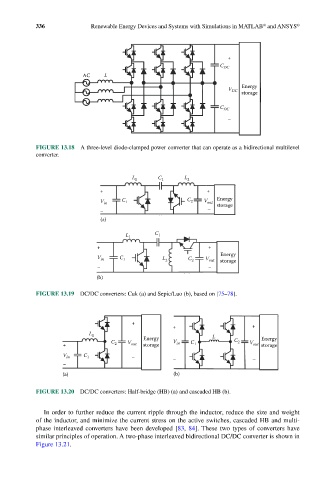
            FIGURE 13.18  A three-level diode-clamped power converter that can operate as a bidirectional multilevel
            converter.


                                         L 1    C 1     L 2
                               +                               +
                                                                  Energy
                               V in   C 1                C 2  V out  storage
                               –                               –
                               (a)


                                       L 1      C 1
                              +                                 +
                                                                   Energy
                              V in   C 1          L 2    C 2   V out  storage
                              –                                 –
                              (b)

            FIGURE 13.19  DC/DC converters: Cuk (a) and Sepic/Luo (b), based on [75–78].


                                         +
                                                     +                       +
                            L 1                                  L
                                  C    V    Energy   V in              C 2      Energy
                    +              2    out  storage      C 1               V out  storage
                    V in  C 1            –           –                       –
                    –
                    (a)                              (b)

            FIGURE 13.20  DC/DC converters: Half-bridge (HB) (a) and cascaded HB (b).


              In order to further reduce the current ripple through the inductor, reduce the size and weight
            of the inductor, and minimize the current stress on the active switches, cascaded HB and multi-
            phase interleaved converters have been developed [83, 84]. These two types of converters have
            similar principles of operation. A two-phase interleaved bidirectional DC/DC converter is shown in
            Figure 13.21.
   344   345   346   347   348   349   350   351   352   353   354