
Page 350 - Renewable Energy Devices and System with Simulations in MATLAB and ANSYS
P. 350
Batteries and Ultracapacitors for Electric Power Systems with Renewable Energy Sources 337
+
L
Energy
C 2 V out
+ storage
V in C 1
– –
FIGURE 13.21 Two-phase interleaved bidirectional converter.
L 1 +
C 2
+
Energy
V in C 1 V out storage
C 2
–
FIGURE 13.22 Three-level neutral point clamped bidirectional DC/DC converter.
Bidirectional three-level DC/DC converters, as illustrated in Figure 13.22, have been developed
for high DC link voltage applications, in order to lower the switch voltage stress on the switches and
minimize the passive elements, inductors and capacitors, in comparison with HB converters. Due
to the reduced switch voltage stress, switching can be performed with a lower voltage rate, yielding
lower on-state voltage and switching losses [84].
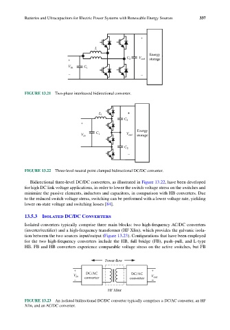
13.5.3 Isolated DC/DC Converters
Isolated converters typically comprise three main blocks: two high-frequency AC/DC converters
(inverter/rectifier) and a high-frequency transformer (HF Xfm), which provides the galvanic isola-
tion between the two sources input/output (Figure 13.23). Configurations that have been employed
for the two high-frequency converters include the HB, full bridge (FB), push–pull, and L-type
HB. FB and HB converters experience comparable voltage stress on the active switches, but FB
Power flow
+ +
DC/AC DC/AC
V in converter V out
– converter –
HF Xfmr
FIGURE 13.23 An isolated bidirectional DC/DC converter typically comprises a DC/AC converter, an HF
Xfm, and an AC/DC converter.