
Page 342 - Renewable Energy Devices and System with Simulations in MATLAB and ANSYS
P. 342
Batteries and Ultracapacitors for Electric Power Systems with Renewable Energy Sources 329
C ss R ss
+ +
R s
C o Terminal
OCV R sd voltage
– –
FIGURE 13.9 Electric equivalent circuit model for an ultracapacitor. (Based on the concept proposed in
Manla, E. et al., Proceedings of Energy Conversion Congress and Exposition (ECCE), pp. 2957–2962, 2011.)
response of an ultracapacitor. The parameter identification requires multiple AC and DC tests. The
equivalent incremental internal capacitance is calculated as
0 (
i
COCV i) = ∆ Q i ∑ i It ()∆ t (13.4)
=
∆ OCV i ∆ OCV i
where
OCV is the open-circuit voltage
I is the current
Q is the columbic charge for the data point i
It should be noted that a columbic counting technique has been employed to estimate the SOC,
which varies approximately linearly with OCV.
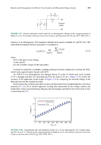
An 1100 F Li-ion ultracapacitor was charged during 16 cycles in which each cycle consists
of 10 s charging and then rest (disconnected from the source) for 20 s. Figure 13.10 verifies the
accuracy of the equivalent circuit model of Figure 13.9 by comparing the terminal voltage of the
ultracapacitor and the simulation model.
Some models that combine equivalent circuits and electrochemistry fundamentals have also been
proposed [31, 32]. Yet in another approach, training data represented by the voltage, current, and
temperature values measured during charging and discharging experiments have been used to train
a neural network [37].
4
Simulation
3.5 Test
Voltage (V) 3
2.5
0
0 60 120 180 240 300 360 420 480
Time (s)
FIGURE 13.10 Experimental data and simulation results for a Li-ion ultracapacitor, 10 A pulsed charg-
ing DC test at 25 °C. (Based on the concept proposed in Manla, E. et al., Proceedings of Energy Conversion
Congress and Exposition (ECCE), pp. 2957–2962, 2011.)