
Page 356 - Renewable Energy Devices and System with Simulations in MATLAB and ANSYS
P. 356
Batteries and Ultracapacitors for Electric Power Systems with Renewable Energy Sources 343
13.7 SIMULATION EXAMPLES
13.7.1 EV Charging Station
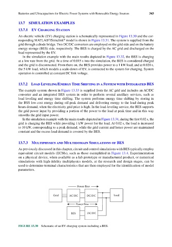
An electric vehicle (EV) charging station is schematically represented in Figure 13.30 and the cor-
®
®
responding MATLAB /Simulink model is shown in Figure 13.31. The system is supplied from the
grid through a diode bridge. Two DC/DC converters are employed on the grid side and on the battery
energy storage (BES) side, respectively. The BES is charged by the AC grid and discharged on the
load represented by the EV.
In the simulation example with the main results depicted in Figure 13.32, the BES is charging
at a low rate from the grid. At a time of 0.015 s into the simulation, the BES is considered charged
and the grid is disconnected. From there on, the BES provides power to a 1 kW load, and at 0.020 s,
the 5 kW load, which models a scale-down of EV, is connected to the system for charging. System
operation is controlled at constant DC link voltage.
13.7.2 Load Leveling/Energy Time Shifting in a System with Integrated BES
The example system shown in Figure 13.33 is supplied from the AC grid and includes an AC/DC
converter and an integrated BES system in order to perform several ancillary services, such as
load leveling and energy time shifting. The system performs energy time shifting by storing in
the BSS low-cost energy during off-peak demand and delivering energy to the load during peak
hours demand, when the electricity grid price is high. In the load-leveling service, the BES supports
the grid power input by providing a portion of the power to the load at peak time and in this way
smooths the grid input power.
In the simulation example with the main results depicted in Figure 13.34, during the first 0.02 s, the
grid is charging the BES while providing 1 kW power for the load. At 0.02 s, the load is increased
to 10 kW, corresponding to a peak demand, while the grid current and hence power are maintained
constant and the excess load demand is covered by the BES.
13.7.3 Multiphysics and Multidomain Simulations of BES
As previously discussed in this chapter, circuit and control simulations with BES typically employ
equivalent circuit models (ECMs), such as those exemplified in Figure 13.4. Experimentation
on a physical device, when available as a lab prototype or manufactured product, or numerical
simulations with high-fidelity multiphysics models, at the research and design stages, can be
used to determine terminal characteristics that are then employed for the identification of model
parameters.
Power flow
Grid AC/DC DC/DC Load
Power flow
BES DC/DC
FIGURE 13.30 Schematic of an EV charging system including a BES.