
Page 360 - Renewable Energy Devices and System with Simulations in MATLAB and ANSYS
P. 360
Batteries and Ultracapacitors for Electric Power Systems with Renewable Energy Sources 347
DC link voltage (V DC )
500
Voltage (V) 400
300
200
0 0.005 0.01 0.015 0.02 0.025 0.03 0.035 0.04 0.045 0.05
Grid current (i-grid)
100
Current (A) 50 0
–50
0 0.005 0.01 0.015 0.02 0.025 0.03 0.035 0.04 0.045 0.05
BES current (i-BES)
50
Current (A) 0
–50
0 0.005 0.01 0.015 0.02 0.025 0.03 0.035 0.04 0.045 0.05
Load power
15
Power (kW) 10 5
0
0 0.005 0.01 0.015 0.02 0.025 0.03 0.035 0.04 0.045 0.05
Time (s)
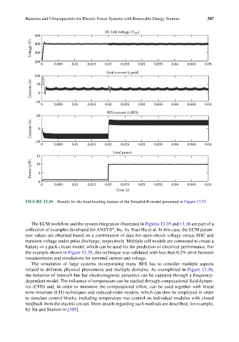
FIGURE 13.34 Results for the load-leveling feature of the Simulink® model presented in Figure 13.33.
The ECM workflow and the system integration illustrated in Figures 13.35 and 13.36 are part of a
®
collection of examples developed for ANSYS , Inc. by Xiao Hu et al. In this case, the ECM param-
eter values are obtained based on a combination of data for open-circuit voltage versus SOC and
transient voltage under pulse discharge, respectively. Multiple cell models are connected to create a
battery or a pack circuit model, which can be used for the prediction of electrical performance. For
the example shown in Figure 13.35, this technique was validated with less than 0.2% error between
measurements and simulations for terminal current and voltage.
The simulation of large systems incorporating many BES has to consider multiple aspects
related to different physical phenomena and multiple domains. As exemplified in Figure 13.36,
the behavior of intercell bus bar electromagnetic parasitics can be captured through a frequency-
dependent model. The influence of temperature can be studied through computational fluid dynam-
ics (CFD) and, in order to minimize the computational effort, can be used together with linear
time-invariant (LTI) techniques and reduced-order models, which can then be employed in order
to simulate control blocks, including temperature rise control on individual modules with closed
feedback from the electric circuit. More details regarding such methods are described, for example,
by Xu and Stanton in [105].