
Page 39 - Renewable Energy Devices and System with Simulations in MATLAB and ANSYS
P. 39
26 Renewable Energy Devices and Systems with Simulations in MATLAB and ANSYS ®
®
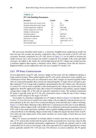
TABLE 2.1
PV Cell Modeling Parameters
Parameter Symbol Value
Nominal string short-circuit current I scn 4 A
Nominal string open-circuit voltage V ocn 0.58 V
Current temperature coefficient K i 0.001 A/K
Voltage temperature coefficient K v −0.002 V/K
Number of cells in series N s 1
Nominal irradiance G n 1000 W/m 2
Nominal cell temperature T n 298.15 K
Boltzmann’s constant k 1.3807 × 10 J·K −1
−23
−19
Electron charge q 1.60217662 × 10 C
Diode ideality factor a 1.3
The previously described ideal model is a relatively straightforward mathematical model but
does not take into account any parasitic components; thus, it does not model a real PV cell very
accurately. Parasitic components in a PV cell, shown in Figure 2.5, can be added to increase the
model accuracy, but it also increases the model’s complexity. For example, if the series and shunt
resistance are added to the model, the relationship between the PV voltage and current becomes
a nonlinear equation that requires a nonlinear solver. Often, a nonlinear solver, like the Newton–
Raphson method, can be employed to solve the more complex PV models [10].
2.2.3 PV Panel Configuration
In most applications using PV cells, not just a single cell but many cells are combined to produce a
larger amount of power. When added together, the PV cells can be connected in series, parallel, or a
combination of both. When cells are connected in series, their voltages are summed together. When
cells are connected in parallel, their currents are summed together. A single silicon cell tends to pro-
duce around 0.5 V for voltage and current that is proportional to the cell’s surface area. The decision
to connect PV cells in series or parallel is often determined by the voltage and current needs of the
application. Most PV applications today, like rooftop PV installations and satellites, require a higher
voltage than a single cell, so the cells are typically connected in series. The standard commercial
PV panel is typically made up of 72–96 cells connected in series so that the sum of their voltages
achieves overall voltages in the range of 30–60 V.
An example of connection configuration of a PV panel is shown in Figure 2.12 that has 72 cells
in series. To cover the area of a panel (one series string), cells are typically connected down one col-
umn and back up the next. Each series connection that goes down and back up is called a substring.
Figure 2.12 shows three substrings with a diode that is connected across the ends of each substring.
This diode is called a bypass diode, which allows for an additional current path around the substring
if PV cells in that string experience a problem, such as partial shading, permanent degradation, or a
connection break in the substring. Bypass diodes help to reduce the degree that these kinds of prob-
lems affect the total output power of the panel, but there are various types of faults that can occur
in a panel [14].
Many PV systems are installed on rooftops and/or in remote areas that are not easily service-
able, so PV systems that include both the panels and the associated power electronics must be able
to work properly with minimal maintenance requirements. PV panels are typically rated to work
continuously for 25 years or even longer, with some expected level of natural degradation in output
power, generally around 0.5%–1.0% per year [10]. However, in certain conditions, the PV panels