
Page 164 - Reservoir Geomechanics
P. 164
147 Faults and fractures at depth
a. b.
FLUX-GATE
MAGNETOMETER
PIEZOELECTRIC
MOTOR TRANSDUCER
h
Travel time
Amplitude
Sync
Signal d
Pulse
c. d. N E S W N
MN
133
PARTIAL
SINUSOID
STRIKE 137
Depth [meters] FRACTURES
141
h
145
Dip = tan (h/d)
−1
strike
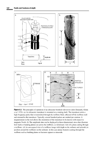
Figure 5.3. The principles of operation of an ultrasonic borehole televiewer (after Zemanek, Glenn
et al. 1970). (a) An ultrasonic transducer is mounted on a rotating shaft. The transducer emits a
high-frequency pulse that is transmitted through the wellbore fluid, reflected off the wellbore wall
and returned to the transducer. Typically, several hundred pulses are emitted per rotation. A
magnetometer in the tool allows the orientation of the transducer to be known with respect to
magnetic North. (b) The amplitude data can be displayed in three-dimensional views that illustrate
how faults or bedding planes cut across the wellbore. (c) Schematic view of a plane cutting through
a wellbore. (d) An unwrapped view of a wellbore image with depth on the ordinate and azimuth (or
position around the wellbore) on the ordinate. In this case planar features scutting through the
wellbore such as bedding planes or fractures appear as sinusoids.