
Page 165 - Reservoir Geomechanics
P. 165
148 Reservoir geomechanics
a. b.
0 64 128 256
N E S W N
6000
TELEMETRY
6002
INSULATING SUB
FAD CONFIGURATION
6004
AMPLIFICATION
CARTRIDGE
INSULATING 27 Buttons
SLEEVE 8.2 in diameter
58% overlap
FLEX JOINT Depth (feet) 6008
Side by side
INCLINOMETER
SHOT button
PREAMP
CARTRIDGE 6010
HYDRAULICS
6012
FOUR-ARM SONDE
6014
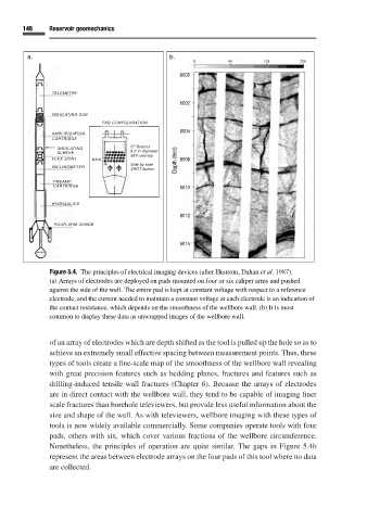
Figure 5.4. The principles of electrical imaging devices (after Ekstrom, Dahan et al. 1987).
(a) Arrays of electrodes are deployed on pads mounted on four or six caliper arms and pushed
against the side of the well. The entire pad is kept at constant voltage with respect to a reference
electrode, and the current needed to maintain a constant voltage at each electrode is an indication of
the contact resistance, which depends on the smoothness of the wellbore wall. (b) It is most
common to display these data as unwrapped images of the wellbore wall.
of an array of electrodes which are depth shifted as the tool is pulled up the hole so as to
achieve an extremely small effective spacing between measurement points. Thus, these
types of tools create a fine-scale map of the smoothness of the wellbore wall revealing
with great precision features such as bedding planes, fractures and features such as
drilling-induced tensile wall fractures (Chapter 6). Because the arrays of electrodes
are in direct contact with the wellbore wall, they tend to be capable of imaging finer
scale fractures than borehole televiewers, but provide less useful information about the
size and shape of the well. As with televiewers, wellbore imaging with these types of
tools is now widely available commercially. Some companies operate tools with four
pads, others with six, which cover various fractions of the wellbore circumference.
Nonetheless, the principles of operation are quite similar. The gaps in Figure 5.4b
represent the areas between electrode arrays on the four pads of this tool where no data
are collected.