
Page 167 - Reservoir Geomechanics
P. 167
150 Reservoir geomechanics
UP
(DIP IS POSITIVE TO
STRIKE
THE RIGHT WHEN
(MEASURED
LOOKING IN THE
FROM NORTH)
STRIKE DIRECTION)
DIP DIRECTION
Dip
(FROM NORTH)
Rake
SLIP
EAST
FAULT PLANE
SOUTH
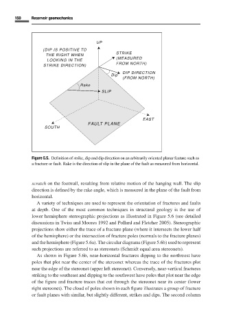
Figure 5.5. Definition of strike, dip and dip direction on an arbitrarily oriented planar feature such as
a fracture or fault. Rake is the direction of slip in the plane of the fault as measured from horizontal.
scratch on the footwall, resulting from relative motion of the hanging wall. The slip
direction is defined by the rake angle, which is measured in the plane of the fault from
horizontal.
Avariety of techniques are used to represent the orientation of fractures and faults
at depth. One of the most common techniques in structural geology is the use of
lower hemisphere stereographic projections as illustrated in Figure 5.6 (see detailed
discussions in Twiss and Moores 1992 and Pollard and Fletcher 2005). Stereographic
projections show either the trace of a fracture plane (where it intersects the lower half
of the hemisphere) or the intersection of fracture poles (normals to the fracture planes)
and the hemisphere (Figure 5.6a). The circular diagrams (Figure 5.6b) used to represent
such projections are referred to as stereonets (Schmidt equal area stereonets).
As shown in Figure 5.6b, near-horizontal fractures dipping to the northwest have
poles that plot near the center of the stereonet whereas the trace of the fractures plot
near the edge of the stereonet (upper left stereonet). Conversely, near-vertical fractures
striking to the southeast and dipping to the southwest have poles that plot near the edge
of the figure and fracture traces that cut through the stereonet near its center (lower
right stereonet). The cloud of poles shown in each figure illustrates a group of fracture
or fault planes with similar, but slightly different, strikes and dips. The second column