
Page 450 - Robot Builder's Bonanza
P. 450
CREATING ELECTRONIC CIRCUIT BOARDS WITH PCB CAD 419
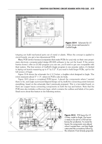
Figure 33- 4 Schematic for L’il
Cricket, drawn and executed in
CadSoft Eagle.
totyping can build mechanical parts out of metal or plastic. When the concept is applied to
circuit boards, you get a two- dimensional PCB.
Many PCB service bureaus (companies that make PCBs for you) rely on their own propri-
etary electronic computer- aided design (ECAD) software to lay out the board. If the service
bureau doesn’t offer an ECAD program you can use, you’ll need to get one compatible with
their system. The free version of CadSoft’s Eagle program is one popular option; it’s limited
to laying out boards measuring up to 4″ by 3.2″. If you need to build larger PCBs, opt for the
full version of Eagle.
Figure 33- 4 shows the schematic for L’il Cricket, a buglike robot designed in Eagle. The
robot measures about 5″ 3″, where its PCB is also its body.
Figure 33- 5 shows a completed PCB layout. I placed the components where I wanted
them to be, and Eagle autorouted (figured things out by itself) the connecting points between
everything, based on the schematic that I previously prepared. This is a two- sided board, so
there are copper traces connecting components on both the top and bottom. Note that the
PCB view also includes a silkscreen layer, which contains the outlines and labels of the parts.
Read more about this feature in the following section.
Figure 33- 5 PCB layout for L’il
Cricket, made by Eagle. The layout
is ready to be sent to a PCB service
bureau for production. To create the
layout, the components were placed
where I wanted them, and then Eagle
autorouted the connections following
the schematic I had already prepared.
33-chapter-33.indd 419 4/21/11 11:56 AM