
Page 447 - Robot Builder's Bonanza
P. 447
416 MAKING CIRCUIT BOARDS
The solderboard comes pre- etched with 550 tie points. Circuits may be designed on a
solderless breadboard, then transferred to the solder board when you’re sure everything is
working to your liking. Simply solder the components into place following the same design
you used on the solderless board. Use jumper wires to connect components that can’t be
directly tied together. Figure 33- 1 shows both a solderless and a solder breadboard.
Small circuits take up only a portion of the solder breadboard. You can cut off the extra
using a hacksaw or razor saw. (But beware of the “sawdust” from these boards; it’s not healthy
for you, so don’t inhale or ingest any of it.) Leave space in the corners of the board to drill new
mounting holes, so that you can secure the board inside whatever enclosure you are using.
Alternatively, you can secure the board to a frame or inside an enclosure using double- sided
foam tape.
If you’re constructing small circuits, one solderboard will last for several projects. In time,
you’ll learn how to conserve space to make good use of the real estate on a solderboard.
Using Point- to- Point Perforated
Board Construction
An alternative to the solder breadboard is point- to- point perforated (or “perf”) circuit board
construction. This technique refers to mounting the components on a predrilled board and
connecting the leads together directly with solder. Perf boards are basically just blank pieces
of phenolic or other plastic, with holes drilled every 0.1″. This is the correct spacing for stan-
dard integrated circuits, and it works well for other components.
For robot electronics, point- to- point perf board construction is best used— if at all— for very
simple circuits containing just a few components. You use the board as a kind of structure for
the electronic parts.
BUILDING A CIRCUIT ON A PERF BOARD
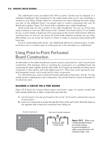
Figure 33- 2 shows the concept behind using a perf board— again, it’s merely a board with
holes already drilled into it. Basic construction goes like this:
1. Cut the board to the size you’ll need for the circuit. You’ll need to estimate the amount
of board space.
2. Insert one component at a time through the holes of the perf board. Bend the leads on
the opposite side to keep the component from falling out.
Top view of bare board Side view of mounted components
Figure 33- 2 When using
Connect and solder a perforated (perf) board,
components leads
or wires directly you directly connect
components together or
solder component leads with
insulated jumper wires.
33-chapter-33.indd 416 4/21/11 11:56 AM