
Page 188 -
P. 188
4.2 Path Generation 171
Converting Cartesian Trajectories to Joint Space
In robotic applications, a desired task is usually specified in the workspace or
Cartesian space, as this is where the motion of the manipulator is easily
described in relation to the external environment and workpiece. However,
trajectory-following control is easily performed in the joint space, as this is
where the arm dynamics are more easily formulated.
Therefore, it is important to be able to find the desired joint space trajectory
q d (t) given the desired Cartesian trajectory. This is accomplished using the
inverse kinematics, as shown in the next example. The example illustrates
that the mapping of Cartesian to joint space trajectories may not be unique-
that is, several joint space trajectories may yield the same Cartesian trajectory
for the end-effector.
EXAMPLE 4.2–1: Mapping a Prescribed Cartesian Trajectory to Joint
Space
In Example A.3–5 are derived the inverse kinematics for the two-link planar
robot arm shown in Figure 4.2.1. Let us use them to convert a path from
Cartesian space to joint space.
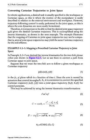
Suppose that we want the two-link arm to follow a given workspace or
Cartesian trajectory
p(t)=(x(t), y(t)) (1)
in the (x, y) plane which is a function of time t. Since the arm is moved by
actuators that control its angles 1, 2, it is convenient to convert the specified
Cartesian trajectory (x(t), y(t)) into a joint space trajectory ( 1(t), 2(t)) for
control purposes.
This may be achieved by using the inverse kinematics transformations
2
2
r =x +y 2 (2)
(3)
(4)
2 =ATAN2 (D, C) (5)
Copyright © 2004 by Marcel Dekker, Inc.