
Page 111 - Robot Builders Source Book - Gordon McComb
P. 111
100 Dynamic Analysis of Drives
the shortest possible time followed by locking of the drive as soon as the moving
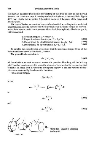
element has come to a stop. A braking mechanism is shown schematically in Figure
3.27. Here 1 is the driving motor, 2 the driven machine, 3 the drum of the brake, and
4 brake shoes.
The type of brakes we consider here can be classified according to the analytical
approximation used to characterize the dependence of the brake torque on the vari-
ables of the system under consideration. Thus, the following kinds of brake torque T b
will be analyzed:
To simplify the consideration we assume that the resistance torque T T for all the
cases mentioned above is constant: T r = const.
The general brake equation is
All the solutions we seek here must answer the question: How long will the braking
take? In other words, we need to know the amount of time needed for the moving part
to reduce its speed from a value CD to a complete stop CD = 0, and the value of the dis-
placement executed by the element in that time.
For constant torque,
hence
or
and
FIGURE 3.27 Layout of a braking
mechanism.
TEAM LRN