
Page 195 - Robot Builders Source Book - Gordon McComb
P. 195
5.1 Linear and Angular Displacement Sensors 183
FIGURE 5.11 Analog optical displacement sensor.
toelectric element that has a variable response to illumination along its surface. When
a diaphragm 1 with a narrow slit 2 moves along optical wedge 3, the latter's response
corresponds to the relative position of these elements. It is not a highly sensitive device.
However, there are situations where it is appropriate.
Pneumatic sensors
We now consider pneumatic sensors. The basic model we will consider is shown
in Figure 5. 12. Its main elements are the nozzles in sections I and II. Let us consider
the continuity of flow through these nozzles, which is described in the following form:
Here,
a lt a 2 = coefficient of flow rates in sections I and II, respectively,
fi> fz = cross-sectional areas of the nozzles I and II,
p = density of the gas, assumed to be constant,
V lt V 2 - velocities of gas flow within I and II,
H=working pressure before nozzle I,
h = working pressure before nozzle II.
Now we make some assumptions: first, that the gas density in the two sections is prac-
tically equal; second:
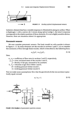
FIGURE 5.12 TEAM LRN
Layout of pneumatic position sensor.