
Page 197 - Robot Builders Source Book - Gordon McComb
P. 197
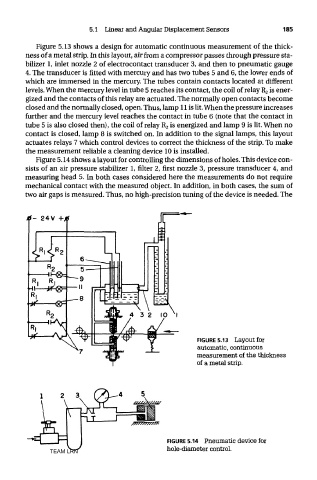
5.1 Linear and Angular Displacement Sensors            185

           Figure 5.13 shows a design for automatic continuous measurement of the thick-
        ness of a metal strip. In this layout, air from a compressor passes through pressure sta-
        bilizer 1, inlet nozzle 2 of electrocontact transducer 3, and then to pneumatic gauge
        4. The transducer is fitted with mercury and has two tubes 5 and 6, the lower ends of
        which are immersed in the mercury. The tubes contain contacts located at different
        levels. When the mercury level in tube 5 reaches its contact, the coil of relay R 2 is ener-
        gized and the contacts of this relay are actuated. The normally open contacts become
        closed and the normally closed, open. Thus, lamp 11 is lit. When the pressure increases
        further and the mercury level reaches the contact in tube 6 (note that the contact in
        tube 5 is also closed then), the coil of relay R 2 is energized and lamp 9 is lit. When no
        contact is closed, lamp 8 is switched on. In addition to the signal lamps, this layout
        actuates relays 7 which control devices to correct the thickness of the strip. To make
        the measurement reliable a cleaning device 10 is installed.
           Figure 5.14 shows a layout for controlling the dimensions of holes. This device con-
        sists of an air pressure stabilizer 1, filter 2, first nozzle 3, pressure transducer 4, and
        measuring head 5. In both cases considered here the measurements do not require
        mechanical contact with the measured object. In addition, in both cases, the sum of
        two air gaps is measured. Thus, no high-precision tuning of the device is needed. The


                                                          FIGURE 5.13  Layout for
                                                          automatic, continuous
                                                          measurement of the thickness
                                                          of a metal strip.


                                                  FIGURE 5.14  Pneumatic device for
               TEAM LRN                          hole-diameter control.