
Page 199 - Robot Builders Source Book - Gordon McComb
P. 199
5.1 Linear and Angular Displacement Sensors 187
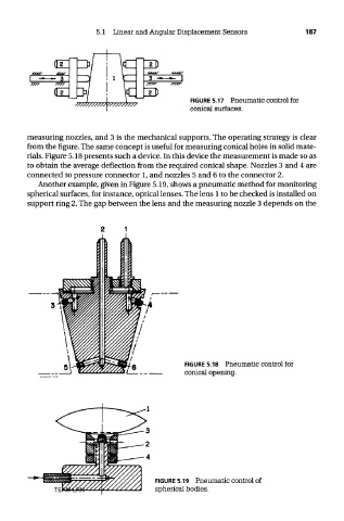
FIGURE 5.17 Pneumatic control for
conical surfaces.
measuring nozzles, and 3 is the mechanical supports. The operating strategy is clear
from the figure. The same concept is useful for measuring conical holes in solid mate-
rials. Figure 5.18 presents such a device. In this device the measurement is made so as
to obtain the average deflection from the required conical shape. Nozzles 3 and 4 are
connected to pressure connector 1, and nozzles 5 and 6 to the connector 2.
Another example, given in Figure 5.19, shows a pneumatic method for monitoring
spherical surfaces, for instance, optical lenses. The lens 1 to be checked is installed on
support ring 2. The gap between the lens and the measuring nozzle 3 depends on the
FIGURE 5.18 Pneumatic control for
conical opening.
FIGURE 5.19 Pneumatic control of
TEAM LRN spherical bodies.