
Page 49 - Robot Builders Source Book - Gordon McComb
P. 49
38 Concepts and Layouts
While the layout sketch need not be to scale, it must clearly explain our concept of
the process. Some examples follow. The first of these is a discontinuous process where
the operations appear stepwise one after the other. The second example, by contrast,
is a continuous process for producing spiral springs.
Example I
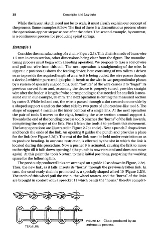
Consider the manufacturing of a chain (Figure 2.1). This chain is made of brass wire
1.5 mm in cross section, other dimensions being clear from the figure. The manufac-
turing process must begin with a feeding operation. We propose to take a coil of wire
and pull out wire from this coil. The next operation is straightening of the wire. In
Figure 2.2 position a) shows the feeding device, here consisting of two rollers 1 driven
so as to provide the required length of wire. As it is being pulled, the wire passes through
a device 2 which imparts multiple plastic bends to the wire in two perpendicular planes
by a system of specially shaped pins. Such "torture" of the wire causes it to "forget" its
previous curved form and, assuming the device is properly tuned, provides straight
wire after the feeder. A length of wire corresponding to that needed for one link is mea-
sured out in our example, 85 mm. The next operation is cutting the measured section
by cutter 3. While fed and cut, the wire is passed through a slot created on one side by
a shaped support 4 and on the other side by two parts of a horseshoe-like tool 5. The
shape of support 4 matches the inner contour of a single link. At the next operation
the pair of tools 5 moves to the right, bending the wire section around support 4.
Towards the end of the bending process tool 5 pinches the "horns" of the link inwards,
completing the shape of the link. Pins 6 fetch the tools 5 to perform this movement.
The latter operations are illustrated in Figure 2.2b) and c). Next a punch 7 drops down
and bends the ends of the link. An opening 8 guides the punch and provides a place
for the link (see Figure 2.2d)). The rest of the link must be held under restriction so as
to produce bending. In our case restriction is effected by the slot in which the link is
located during this procedure. Now a pusher 9 is actuated, causing the link to move
to the right till it falls down opening 8 (the punch is now retracted and does not move
again). At this point the tools 5 return to their initial positions, preparing the working
space for the following link.
The previously produced links are arranged on a guide 12 as shown in Figure, 2.2e).
Thus, the new link, as it falls, inserts its "horns" through the previously fallen link. In
turn, the semi-ready chain is promoted by a specially shaped wheel 10 (Figure 2.2f)).
The teeth of this wheel pull the chain, the wheel rotates, and the "horns" of the links
are brought in contact with a sprocket 11 which bends the "horns," thereby complet-
FIGURE 2.1 Chain produced by an
automatic process.
TEAM LRN