
Page 51 - Robot Builders Source Book - Gordon McComb
P. 51
40 Concepts and Layouts
ing the process of production of this chain, The completed chain is received by the
sprocket 11 rotating at an appropriate speed.
Example 2
Consider an automatic machine for the mass production of springs made of steel
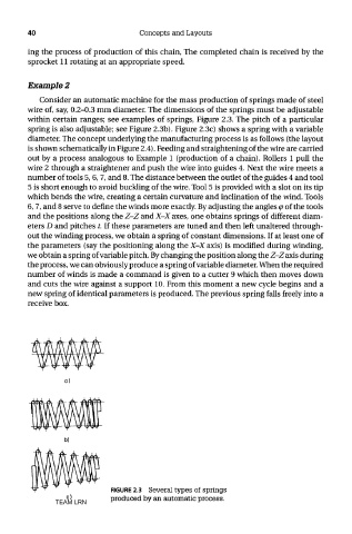
wire of, say, 0.2-0.3 mm diameter. The dimensions of the springs must be adjustable
within certain ranges; see examples of springs, Figure 2.3. The pitch of a particular
spring is also adjustable; see Figure 2.3b). Figure 2.3c) shows a spring with a variable
diameter. The concept underlying the manufacturing process is as follows (the layout
is shown schematically in Figure 2.4). Feeding and straightening of the wire are carried
out by a process analogous to Example 1 (production of a chain). Rollers 1 pull the
wire 2 through a straightener and push the wire into guides 4. Next the wire meets a
number of tools 5,6,7, and 8. The distance between the outlet of the guides 4 and tool
5 is short enough to avoid buckling of the wire. Tool 5 is provided with a slot on its tip
which bends the wire, creating a certain curvature and inclination of the wind. Tools
6,7, and 8 serve to define the winds more exactly. By adjusting the angles cp of the tools
and the positions along the Z-Z and X-X axes, one obtains springs of different diam-
eters D and pitches t. If these parameters are tuned and then left unaltered through-
out the winding process, we obtain a spring of constant dimensions. If at least one of
the parameters (say the positioning along the X-X axis) is modified during winding,
we obtain a spring of variable pitch. By changing the position along the Z-Z axis during
the process, we can obviously produce a spring of variable diameter. When the required
number of winds is made a command is given to a cutter 9 which then moves down
and cuts the wire against a support 10. From this moment a new cycle begins and a
new spring of identical parameters is produced. The previous spring falls freely into a
receive box.
FIGURE 2.3 Several types of springs
TEAM LRN produced by an automatic process.