
Page 34 - Robotics Designing the Mechanisms for Automated Machinery
P. 34
1.4 Structure of Automatic Industrial Systems 23
FIGURE 1.23 A linear configuration
for an automatic tool.
sides of the block 5), thus facilitating maintenance from the other side. Obviously,
Expression (1.1) is also valid in this case.
The ideal situation occurs when ^ = 0, i.e., where there are no time losses during
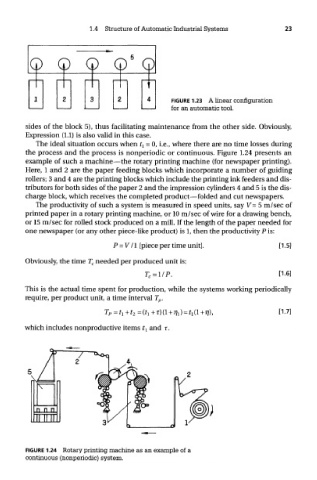
the process and the process is nonperiodic or continuous. Figure 1.24 presents an
example of such a machine—the rotary printing machine (for newspaper printing).
Here, 1 and 2 are the paper feeding blocks which incorporate a number of guiding
rollers; 3 and 4 are the printing blocks which include the printing ink feeders and dis-
tributors for both sides of the paper 2 and the impression cylinders 4 and 5 is the dis-
charge block, which receives the completed product—folded and cut newspapers.
The productivity of such a system is measured in speed units, say V = 5 m/sec of
printed paper in a rotary printing machine, or 10 m/sec of wire for a drawing bench,
or 15 m/sec for rolled stock produced on a mill. If the length of the paper needed for
one newspaper (or any other piece-like product) is 1, then the productivity P is:
Obviously, the time T c needed per produced unit is:
This is the actual time spent for production, while the systems working periodically
require, per product unit, a time interval T p.
which includes nonproductive items t l and T.
FIGURE 1.24 Rotary printing machine as an example of a
continuous (nonperiodic) system.