
Page 30 - Robotics Designing the Mechanisms for Automated Machinery
P. 30
1.3 Manipulators 19
placed in the barrel in such a way that specific items are arranged in each sector 8 of
the barrel. This barrel has only one degree of freedom—it rotates such that it brings
the corresponding sector 8 to the "pick-up" manipulator 7. The manipulator 7 has three
degrees of freedom: it rotates, it moves vertically, and it has a gripper which moves
radially along the lever 9. The barrel and the manipulator act in the following sequence.
The barrel 6 rotates to the required position, and then the gripper of the device 7 picks
up the item. For this purpose the lever 9 faces the corresponding sector of barrel 6 and
moves vertically until the gripper finds itself opposite the required item (obviously the
level of the items in the magazines changes constantly as production proceeds, and
the memory of the machine keeps track of the levels of the items in each magazine of
the barrel 6). After the item has been "caught," the radially moving gripper removes it
from the barrel. The lever rotates through 90°, and then stops at some definite height
which allows it to pass the item to the manipulator 10. The manipulator 10 has two
degrees of freedom, i.e., it rotates, and it has three possible positions at which it stops:
at the first it obtains the item from the lever 9, at the second the leads of the electronic
item are prepared for assembling by the device 11, and at the third the actual assem-
bling takes place. For this latter operation, the lever of the manipulator 10 drops so
that the leads hit the corresponding openings in the X-Ftable which is already in posi-
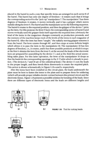
tion. (The devices 6, 7 and 10 are of the cylindrical kind.) The device 11 cuts the leads
to the proper length, and then bends them downwards to create the required pitch.
This action is shown schematically in Figure 1.18 a and b, respectively.
After the items have been installed on the circuit plate, the leads underneath the
plate must be bent to fasten the items to the plate and to prepare them for soldering
(which will provide proper reliable electric contact between the printed circuit and the
electronic items). Figure 1.19 presents a possible solution for bending of the leads. Since
there are different types of electronic items and the leads are different lengths and
FIGURE 1.18 Tool for cutting leads.
FIGURE 1.19 Tool for bending leads.