
Page 32 - Robotics Designing the Mechanisms for Automated Machinery
P. 32
1.4 Structure of Automatic Industrial Systems 21
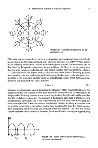
FIGURE 1.20 Circular configuration for an
automatic tool.
Obviously, in many cases there can be several feeding, functional, and inspection blocks
in one machine. The transporting block, which in this case is a rotating table driven
by an indexing mechanism, moves in an interruptive manner. Its movement can be
described by the speed-change form shown in Figure 1.21. Here, it can be clearly seen
that the table moves periodically and each period consists of two components of time,
?!—the duration of movement, and t 2—the duration of the pause. Obviously, both the
functional devices and the loading and discharging blocks can act only when the rotat-
ing table is not in motion and the parts (or semifinished items) are in position under
the tools that handle them. Thus, the ratio
becomes very important since it describes the efficiency of the transporting block. The
higher the ratio, the smaller are the time losses for nonproductive transportation. In
the periodically acting systems some time is required for the idle and auxiliary strokes
that the tools have to execute. For instance, a drill has to approach a part before the
actual drilling operation, and it has to move away from the part after the drilling has
been accomplished. These two actions may be described as auxiliary actions because
no positive processing is carried out during their duration. On the other hand, no pos-
itive processing can be carried out without these two actions. The time the device
spends on these two strokes can, however, be reduced by decreasing the approaching
FIGURE 1.21 Speed-versus-time diagram for an
indexing mechanism.