
Page 28 - Robotics Designing the Mechanisms for Automated Machinery
P. 28
1.3 Manipulators 17
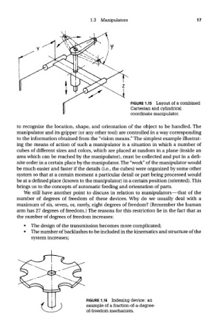
FIGURE 1.15 Layout of a combined
Cartesian and cylindrical
coordinate manipulator.
to recognize the location, shape, and orientation of the object to be handled. The
manipulator and its gripper (or any other tool) are controlled in a way corresponding
to the information obtained from the "vision means." The simplest example illustrat-
ing the means of action of such a manipulator is a situation in which a number of
cubes of different sizes and colors, which are placed at random in a plane (inside an
area which can be reached by the manipulator), must be collected and put in a defi-
nite order in a certain place by the manipulator. The "work" of the manipulator would
be much easier and faster if the details (i.e., the cubes) were organized by some other
system so that at a certain moment a particular detail or part being processed would
be at a defined place (known to the manipulator) in a certain position (oriented). This
brings us to the concepts of automatic feeding and orientation of parts.
We still have another point to discuss in relation to manipulators—that of the
number of degrees of freedom of these devices. Why do we usually deal with a
maximum of six, seven, or, rarely, eight degrees of freedom? (Remember the human
arm has 27 degrees of freedom.) The reasons for this restriction lie in the fact that as
the number of degrees of freedom increases:
• The design of the transmission becomes more complicated;
• The number of backlashes to be included in the kinematics and structure of the
system increases;
FIGURE 1.16 Indexing device: an
example of a fraction-of-a-degree-
of-freedom mechanism.