
Page 82 - Robotics Designing the Mechanisms for Automated Machinery
P. 82
3.2 Electromagnetic Drive 71
Here 0 is calculated from the initial conditions £ = 0,0 = 0 0, and 0 = 0, and has the form
3.2 Electromagnetic Drive
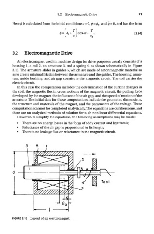
An electromagnet used in machine design for drive purposes usually consists of a
housing 1, a coil 2, an armature 3, and a spring 4, as shown schematically in Figure
3.10. The armature slides in guides 5, which are made of a nonmagnetic material so
as to create minimal friction between the armature and the guides. The housing, arma-
ture, guide bushing, and air gap constitute the magnetic circuit. The coil carries the
electric circuit.
In this case the computation includes the determination of the current changes in
the coil, the magnetic flux in cross sections of the magnetic circuit, the pulling force
developed by the magnet, the influence of the air gap, and the speed of motion of the
armature. The initial data for these computations include the geometric dimensions,
the structure and materials of the magnet, and the parameters of the voltage. These
computations cannot be completed analytically. The equations are cumbersome, and
there are no analytical methods of solution for such nonlinear differential equations.
However, to simplify the equations, the following assumptions may be made:
• There are no energy losses in the form of eddy current and hysteresis;
• Reluctance of the air gap is proportional to its length;
• There is no leakage flux or reluctance in the magnetic circuit.
FIGURE 3.10 Layout of an electromagnet.