
Page 86 - Robotics Designing the Mechanisms for Automated Machinery
P. 86
3.3 Electric Drives 75
3.3 Electric Drives
In this section we consider the behavior of electrically driven mechanical systems.
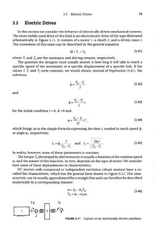
The most widely used drive of this kind is an electromotor drive of the type illustrated
schematically in Figure 3.11. It consists of a motor 1, a clutch 2, and a driven mass /.
The movement of this mass can be described by the general equation
where T r and T d are the resistance and driving torques, respectively.
The question the designer must usually answer is how long it will take to reach a
specific speed of the movement or a specific displacement of a specific link. If the
values /, T r and T d were constant, we would obtain, instead of Expression (3.41), the
solutions
and
for the initial condition t = 0, 0 = 0 and
which brings us to the simple formula expressing the time ^ needed to reach speed ^
or angle (j> lf respectively:
In reality, however, none of these parameters is constant.
The torque T d developed by electromotors is usually a function of the rotation speed
CD, and the nature of this function, in turn, depends on the type of motor. We consider
here some of these dependencies or characteristics.
DC motors with compound or independent excitation (shunt motors) have a so-
called flat characteristic, which has the general form shown in Figure 3.12. This char-
acteristic can be usually approximated by a straight line and can therefore be described
analytically in a corresponding manner:
FIGURE 3.11 Layout of an electrically driven machine.