
Page 90 - Robotics Designing the Mechanisms for Automated Machinery
P. 90
3.3 Electric Drives 79
A special type of electromotor—a stepper motor—is widely used in robotics of dif-
ferent kinds. It is therefore necessary to explain the principle of operation of such
motors and to compare them with the other motors mentioned above.
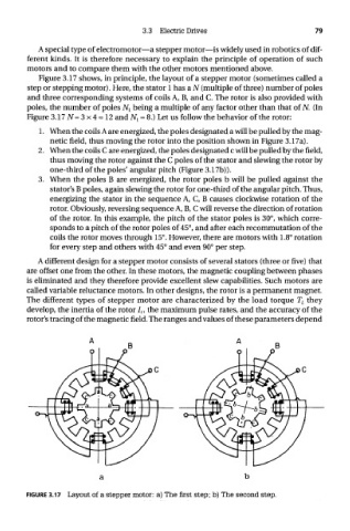
Figure 3.17 shows, in principle, the layout of a stepper motor (sometimes called a
step or stepping motor). Here, the stator 1 has a N (multiple of three) number of poles
and three corresponding systems of coils A, B, and C. The rotor is also provided with
poles, the number of poles N r being a multiple of any factor other than that of N. (In
Figure 3.17^=3x4 = 12 and A/! = 8.) Let us follow the behavior of the rotor:
1. When the coils A are energized, the poles designated a will be pulled by the mag-
netic field, thus moving the rotor into the position shown in Figure 3.17a).
2. When the coils C are energized, the poles designated c will be pulled by the field,
thus moving the rotor against the C poles of the stator and slewing the rotor by
one-third of the poles' angular pitch (Figure 3.17b)).
3. When the poles B are energized, the rotor poles b will be pulled against the
stator's B poles, again slewing the rotor for one-third of the angular pitch. Thus,
energizing the stator in the sequence A, C, B causes clockwise rotation of the
rotor. Obviously, reversing sequence A, B, C will reverse the direction of rotation
of the rotor. In this example, the pitch of the stator poles is 30°, which corre-
sponds to a pitch of the rotor poles of 45°, and after each recommutation of the
coils the rotor moves through 15°. However, there are motors with 1.8° rotation
for every step and others with 45° and even 90° per step.
A different design for a stepper motor consists of several stators (three or five) that
are offset one from the other. In these motors, the magnetic coupling between phases
is eliminated and they therefore provide excellent slew capabilities. Such motors are
called variable reluctance motors. In other designs, the rotor is a permanent magnet.
The different types of stepper motor are characterized by the load torque T L they
develop, the inertia of the rotor I r, the maximum pulse rates, and the accuracy of the
rotor's tracing of the magnetic field. The ranges and values of these parameters depend
FIGURE 3.17 Layout of a stepper motor: a) The first step; b) The second step.