
Page 91 - Robotics Designing the Mechanisms for Automated Machinery
P. 91
80 Dynamic Analysis of Drives
on the design and dimensions of the motors. These parameters usually change in the
following range:
Torque: T L =22.5 -1125 kg m,
2
Inertia of the rotor: I r = 1.2-10000 g cm ,
Maximum pulse rate: S = 150 -5- 50000 pps.
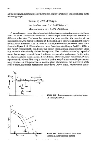
A typical torque-versus-time characteristic for stepper motors is presented in Figure
3.18. The point that should be stressed is that changes in the torque are different for
different pulse rates. The lower the value of the pulse rate (i.e., the duration of one
pulse is longer), the higher the torque at the beginning of the switching and the lower
the torque at the end of it. In more detail, the dependence torque versus pulse rate is
shown in Figure 3.19. (These data are taken from Machine Design, April 29, 1976, p.
36.) Point A represents the conditions that ensure the maximum speed at which a load
can be run bi-directionally without losing a step. This condition occurs by a speed of
about five steps per second. Point B indicates the so-called stall torque. At this point,
the stator windings being energized, for all kinds of motors, resist movement. Point C
represents the detent-like torque which is typical only for motors with permanent
magnet rotors. At this point even a nonenergized stator resists the movement of the
rotor to move. The motor "remembers" its position. Curves 1 and 2 represent the behav-
FIGURE 3.18 Torque-versus-time dependence
for a stepper motor.
FIGURE 3.19 Torque-versus-pulse-rate
dependence for stepper motors.