
Page 138 - Rock Mechanics For Underground Mining
P. 138
ROCK STRENGTH AND DEFORMABILITY
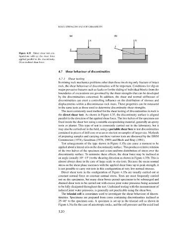
Figure 4.35 Direct shear test con-
figurations with (a) the shear force
applied parallel to the discontinuity,
(b) an inclined shear force.
4.7 Shear behaviour of discontinuities
4.7.1 Shear testing
In mining rock mechanics problems other than those involving only fracture of intact
rock, the shear behaviour of discontinuities will be important. Conditions for slip on
major pervasive features such as faults or for the sliding of individual blocks from the
boundaries of excavations are governed by the shear strengths that can be developed
by the discontinuities concerned. In addition, the shear and normal stiffnesses of
discontinuities can exert a controlling influence on the distribution of stresses and
displacements within a discontinuous rock mass. These properties can be measured
in the same tests as those used to determine discontinuity shear strengths.
The most commonly used method for the shear testing of discontinuities in rock is
the direct shear test. As shown in Figure 4.35, the discontinuity surface is aligned
parallel to the direction of the applied shear force. The two halves of the specimen are
fixed inside the shear box using a suitable encapsulating material, generally an epoxy
resin or plaster. This type of test is commonly carried out in the laboratory, but it
may also be carried out in the field, using a portable shear box to test discontinuities
contained in pieces of drill core or as an in situ test on samples of larger size. Methods
of preparing samples and carrying out these various tests are discussed by the ISRM
Commission (1974), Goodman (1976, 1989) and Hoek and Bray (1981).
Test arrangements of the type shown in Figure 4.35a can cause a moment to be
applied about a lateral axis on the discontinuity surface. This produces relative rotation
of the two halves of the specimen and a non-uniform distribution of stress over the
discontinuity surface. To minimise these effects, the shear force may be inclined at
an angle (usually 10 –15 ) to the shearing direction as shown in Figure 4.35b. This is
◦
◦
almost always done in the case of large-scale in situ tests. Because the mean normal
stress on the shear plane increases with the applied shear force up to peak strength, it
is not possible to carry out tests in this configuration at very low normal stresses.
Direct shear tests in the configuration of Figure 4.35a are usually carried out at
constant normal force or constant normal stress. Tests are most frequently carried
out on dry specimens, but many shear boxes permit specimens to be submerged and
drained shear tests to be carried out with excess joint water pressures being assumed
to be fully dissipated throughout the test. Undrained testing with the measurement of
induced joint water pressures, is generally not practicable using the shear box.
The triaxial cell is sometimes used to investigate the shear behaviour of discon-
tinuities. Specimens are prepared from cores containing discontinuities inclined at
◦
25–40 to the specimen axis. A specimen is set up in the triaxial cell as shown in
Figure 4.34a for the case of anisotropic rocks, and the cell pressure and the axial load
120