
Page 139 - Rock Mechanics For Underground Mining
P. 139
SHEAR BEHAVIOUR OF DISCONTINUITIES
are applied successively. The triaxial cell is well suited to testing discontinuities in the
presence of water. Tests may be either drained or undrained, preferably with a known
level of joint water pressure being imposed and maintained throughout the test.
It is assumed that slip on the discontinuity will occur according to the theory set
out in section 4.6. Mohr circle plots are made of the total or effective stresses at slip
at a number of values of 3 , and the points on these circles giving the stresses on the
plane of the discontinuity are identified. The required shear strength envelope is then
drawn through these points. This requires that a number of tests be carried out on
similar discontinuities.
In an attempt to overcome the need to obtain, prepare and set up several specimens
containing similar discontinuities, a stage testing procedure is sometimes used. A
specimen is tested at a low confining pressure as outlined above. When it appears that
slip on the discontinuity has just been initiated (represented by a flattening of the axial
load–axial displacement curve that must be continuously recorded throughout each
test), loading is stopped, the cell pressure is increased to a new value, and loading
is recommenced. By repeating this process several times, a number of points on the
peak strength envelope of the discontinuity can be obtained from the one specimen.
However, this approach exacerbates the major difficulty involved in using the triaxial
test to determine discontinuity shear strengths, namely the progressive change in the
geometry of the cell–specimen system that accompanies shear displacement on the
discontinuity.
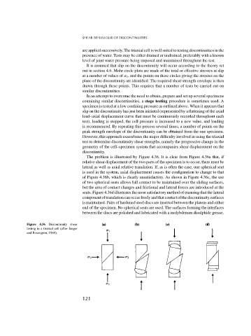
The problem is illustrated by Figure 4.36. It is clear from Figure 4.36a that, if
relative shear displacement of the two parts of the specimen is to occur, there must be
lateral as well as axial relative translation. If, as is often the case, one spherical seat
is used in the system, axial displacement causes the configuration to change to that
of Figure 4.36b, which is clearly unsatisfactory. As shown in Figure 4.36c, the use
of two spherical seats allows full contact to be maintained over the sliding surfaces,
but the area of contact changes and frictional and lateral forces are introduced at the
seats. Figure 4.36d illustrates the most satisfactory method of ensuring that the lateral
componentoftranslationcanoccurfreelyandthatcontactofthediscontinuitysurfaces
is maintained. Pairs of hardened steel discs are inserted between the platens and either
end of the specimen. No spherical seats are used. The surfaces forming the interfaces
between the discs are polished and lubricated with a molybdenum disulphide grease.
Figure 4.36 Discontinuity shear
testing in a triaxial cell (after Jaeger
and Rosengren, 1969).
121