
Page 208 - Rock Mechanics For Underground Mining
P. 208
METHODS OF STRESS ANALYSIS
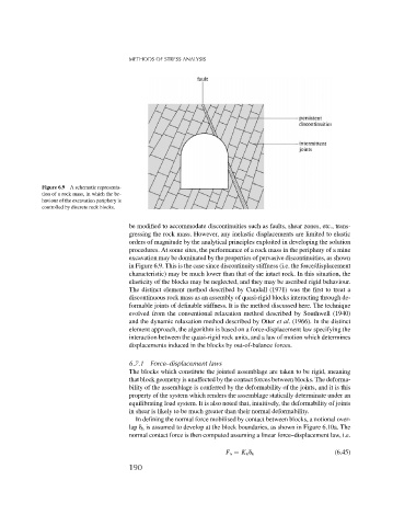
Figure 6.9 A schematic representa-
tion of a rock mass, in which the be-
haviour of the excavation periphery is
controlled by discrete rock blocks.
be modified to accommodate discontinuities such as faults, shear zones, etc., trans-
gressing the rock mass. However, any inelastic displacements are limited to elastic
orders of magnitude by the analytical principles exploited in developing the solution
procedures. At some sites, the performance of a rock mass in the periphery of a mine
excavation may be dominated by the properties of pervasive discontinuities, as shown
in Figure 6.9. This is the case since discontinuity stiffness (i.e. the force/displacement
characteristic) may be much lower than that of the intact rock. In this situation, the
elasticity of the blocks may be neglected, and they may be ascribed rigid behaviour.
The distinct element method described by Cundall (1971) was the first to treat a
discontinuous rock mass as an assembly of quasi-rigid blocks interacting through de-
formable joints of definable stiffness. It is the method discussed here. The technique
evolved from the conventional relaxation method described by Southwell (1940)
and the dynamic relaxation method described by Otter et al. (1966). In the distinct
element approach, the algorithm is based on a force-displacement law specifying the
interaction between the quasi-rigid rock units, and a law of motion which determines
displacements induced in the blocks by out-of-balance forces.
6.7.1 Force–displacement laws
The blocks which constitute the jointed assemblage are taken to be rigid, meaning
that block geometry is unaffected by the contact forces between blocks. The deforma-
bility of the assemblage is conferred by the deformability of the joints, and it is this
property of the system which renders the assemblage statically determinate under an
equilibrating load system. It is also noted that, intuitively, the deformability of joints
in shear is likely to be much greater than their normal deformability.
In defining the normal force mobilised by contact between blocks, a notional over-
lap n is assumed to develop at the block boundaries, as shown in Figure 6.10a. The
normal contact force is then computed assuming a linear force–displacement law, i.e.
F n = K n n (6.45)
190