
Page 290 - Rock Mechanics For Underground Mining
P. 290
ENERGY, MINE STABILITY, MINE SEISMICITY AND ROCKBURSTS
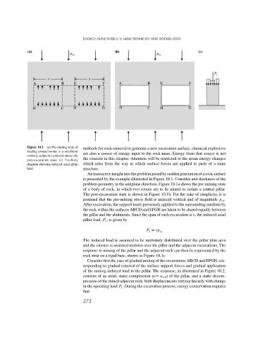
Figure 10.1 (a) Pre-mining state of
methods for rock removal to generate a new excavation surface, chemical explosives
loading around rooms in a stratiform
are also a source of energy input to the rock mass. Energy from that source is not
orebody subject to uniaxial stress; (b)
the concern in this chapter. Attention will be restricted to the strain energy changes
post-excavation state; (c) free-body
diagram showing induced axial pillar which arise from the way in which surface forces are applied to parts of a mine
load. structure.
An instructive insight into the problem posed by sudden generation of a rock surface
is presented by the example illustrated in Figure 10.1. Consider unit thickness of the
problem geometry in the antiplane direction. Figure 10.1a shows the pre-mining state
of a body of rock, in which two rooms are to be mined to isolate a central pillar.
The post-excavation state is shown in Figure 10.1b. For the sake of simplicity, it is
assumed that the pre-mining stress field is uniaxial vertical and of magnitude p zz .
After excavation, the support loads previously applied to the surrounding medium by
the rock within the surfaces ABCD and EFGH are taken to be shared equally between
the pillar and the abutments. Since the span of each excavation is s, the induced axial
pillar load, P z ,isgiven by
P z = sp zz
The induced load is assumed to be uniformly distributed over the pillar plan area
and the closure is assumed uniform over the pillar and the adjacent excavations. The
response to mining of the pillar and the adjacent rock can then be represented by the
rock strut on a rigid base, shown in Figure 10.1c.
Consider first the case of gradual mining of the excavations ABCD and EFGH, cor-
responding to gradual removal of the surface support forces and gradual application
of the mining-induced load to the pillar. The response, as illustrated in Figure 10.2,
consists of an axial, static compression u(= u z st ) of the pillar, and a static decom-
pression of the mined adjacent rock, both displacements varying linearly with change
in the operating load P z . During the excavation process, energy conservation requires
that
272