
Page 403 - Rock Mechanics For Underground Mining
P. 403
DESIGN OF A STOPE-AND-PILLAR LAYOUT
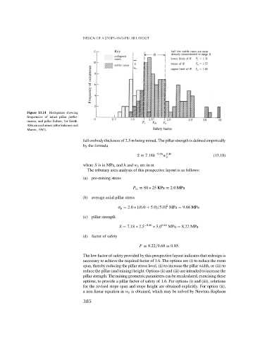
Figure 13.14 Histograms showing
frequencies of intact pillar perfor-
mance, and pillar failure, for South.
African coal mines (after Salamon and
Munro, 1967).
full orebody thickness of 2.5 m being mined. The pillar strength is defined empirically
by the formula
S = 7.18h −0.66 w 0.46 (13.18)
p
where S is in MPa, and h and w p are in m.
The tributary area analysis of this prospective layout is as follows:
(a) pre-mining stress
P zz = 80 ∗ 25 KPa = 2.0MPa
(b) average axial pillar stress
2
p = 2.0 ∗ [(6.0 + 5.0)/5.0] MPa = 9.68 MPa
(c) pillar strength
S = 7.18 ∗ 2.5 −0.66 ∗ 5.0 0.46 MPa = 8.22 MPa
(d) factor of safety
F = 8.22/9.68 = 0.85
The low factor of safety provided by this prospective layout indicates that redesign is
necessary to achieve the required factor of 1.6. The options are (i) to reduce the room
span, thereby reducing the pillar stress level, (ii) to increase the pillar width, or (iii) to
reduce the pillar (and mining) height. Options (ii) and (iii) are intended to increase the
pillar strength. The mining geometric parameters can be recalculated, exercising these
options, to provide a pillar factor of safety of 1.6. For options (i) and (iii), solutions
for the revised stope span and stope height are obtained explicitly. For option (ii),
a non-linear equation in w p is obtained, which may be solved by Newton–Raphson
385