
Page 404 - Rock Mechanics For Underground Mining
P. 404
PILLAR SUPPORTED MINING METHODS
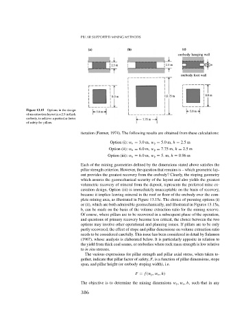
Figure 13.15 Options in the design
of an extraction layout in a 2.5 m thick
orebody, to achieve a particular factor
of safety for pillars.
iteration (Fenner, 1974). The following results are obtained from these calculations:
Option (i): w o = 3.0m,w p = 5.0m, h = 2.5m
Option (ii): w o = 6.0m,w p = 7.75 m, h = 2.5m
Option (iii): w o = 6.0m,w p = 5. m, h = 0.96 m
Each of the mining geometries defined by the dimensions stated above satisfies the
pillar strength criterion. However, the question that remains is – which geometric lay-
out provides the greatest recovery from the orebody? Clearly, the stoping geometry
which assures the geomechanical security of the layout and also yields the greatest
volumetric recovery of mineral from the deposit, represents the preferred mine ex-
cavation design. Option (iii) is immediately unacceptable on the basis of recovery,
because it implies leaving mineral in the roof or floor of the orebody over the com-
plete mining area, as illustrated in Figure 13.15c. The choice of pursuing options (i)
or (ii), which are both admissible geomechanically, and illustrated in Figures 13.15a,
b, can be made on the basis of the volume extraction ratio for the mining reserve.
Of course, where pillars are to be recovered in a subsequent phase of the operation,
and questions of primary recovery become less critical, the choice between the two
options may involve other operational and planning issues. If pillars are to be only
partly recovered, the effect of stope and pillar dimensions on volume extraction ratio
needs to be considered carefully. This issue has been considered in detail by Salamon
(1967), whose analysis is elaborated below. It is particularly apposite in relation to
the yield from thick coal seams, or orebodies where rock mass strength is low relative
to in situ stresses.
The various expressions for pillar strength and pillar axial stress, when taken to-
gether, indicate that pillar factor of safety, F, is a function of pillar dimensions, stope
span, and pillar height (or orebody stoping width), i.e.
F = f (w p ,w o , h)
The objective is to determine the mining dimensions w p ,w o , h, such that in any
386