
Page 408 - Rock Mechanics For Underground Mining
P. 408
PILLAR SUPPORTED MINING METHODS
the reserve. Secondly, fully supported methods using intact, elastic pillars, are lim-
ited economically to low stress settings, or orebodies with high rock mass strength.
Finally, thick seams and orebodies consisting of relatively weak rock masses may
be mined more appropriately and productively in successive phases which are them-
selves based on different design principles, rather than in a single phase of supported
mining.
The usual problem in a pre-feasibility study, preliminary design or initial design of
a supported mining layout is selection of an appropriate pillar strength formula and
of relevant values for a characteristic strength parameter and the scaling exponents.
A reasonable approach may be to employ equation 13.14 to estimate pillar strength,
using the values of K, C 1 and C 2 proposed in Section 13.3. Improved values for
these parameters may then be established as mining progresses in the orebody, by
observations of pillar response to mining, or by large-scale in situ tests. Judicious
reduction in dimensions of selected pillars may be performed in these large-scale
tests, to induce pillar failure.
13.5 Bearing capacity of roof and floor rocks
The discussion of pillar design using the tributary area method assumed implicitly
that a pillar’s support capacity for the country rock was limited by the strength of
the orebody rock. Where hangingwall and footwall rocks are weak relative to the
orebody rock, a pillar support system may fail by punching of pillars into the orebody
peripheral rock. The mode of failure is analogous to bearing capacity failure of a
foundation and may be analysed in a similar way. This type of local response will be
accompanied by heave of floor rock adjacent to the pillar lines, or extensive fretting
and collapse of roof rock around a pillar.
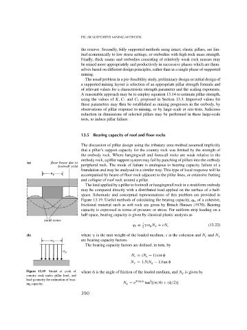
The load applied by a pillar to footwall or hangingwall rock in a stratiform orebody
may be compared directly with a distributed load applied on the surface of a half-
space. Schematic and conceptual representations of this problem are provided in
Figure 13.19. Useful methods of calculating the bearing capacity, q b , of a cohesive,
frictional material such as soft rock are given by Brinch Hansen (1970). Bearing
capacity is expressed in terms of pressure or stress. For uniform strip loading on a
half-space, bearing capacity is given by classical plastic analysis as
1
q b = w p N + cN c (13.22)
2
where is the unit weight of the loaded medium, c is the cohesion and N c and N
are bearing capacity factors.
The bearing capacity factors are defined, in turn, by
N c = (N q − 1) cot
N = 1.5(N q − 1) tan
Figure 13.19 Model of yield of where is the angle of friction of the loaded medium, and N q is given by
country rock under pillar load, and
load geometry for estimation of bear- tan 2
N q = e tan [( /4) + ( /2)]
ing capacity.
390