
Page 412 - Rock Mechanics For Underground Mining
P. 412
PILLAR SUPPORTED MINING METHODS
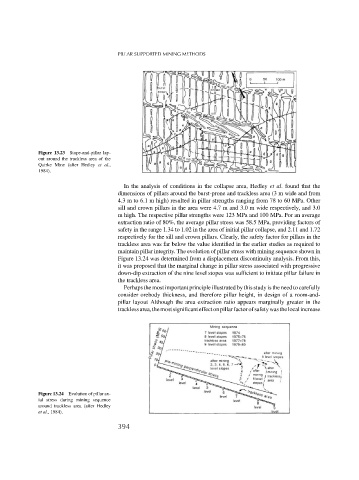
Figure 13.23 Stope-and-pillar lay-
out around the trackless area of the
Quirke Mine (after Hedley et al.,
1984).
In the analysis of conditions in the collapse area, Hedley et al. found that the
dimensions of pillars around the burst-prone and trackless area (3 m wide and from
4.3 m to 6.1 m high) resulted in pillar strengths ranging from 78 to 60 MPa. Other
sill and crown pillars in the area were 4.7 m and 3.0 m wide respectively, and 3.0
m high. The respective pillar strengths were 123 MPa and 100 MPa. For an average
extraction ratio of 80%, the average pillar stress was 58.5 MPa, providing factors of
safety in the range 1.34 to 1.02 in the area of initial pillar collapse, and 2.11 and 1.72
respectively for the sill and crown pillars. Clearly, the safety factor for pillars in the
trackless area was far below the value identified in the earlier studies as required to
maintain pillar integrity. The evolution of pillar stress with mining sequence shown in
Figure 13.24 was determined from a displacement discontinuity analysis. From this,
it was proposed that the marginal change in pillar stress associated with progressive
down-dip extraction of the nine level stopes was sufficient to initiate pillar failure in
the trackless area.
Perhaps the most important principle illustrated by this study is the need to carefully
consider orebody thickness, and therefore pillar height, in design of a room-and-
pillar layout Although the area extraction ratio appears marginally greater in the
tracklessarea,themostsignificanteffectonpillarfactorofsafetywasthelocalincrease
Figure 13.24 Evolution of pillar ax-
ial stress during mining sequence
around trackless area (after Hedley
et al., 1984).
394