
Page 410 - Rock Mechanics For Underground Mining
P. 410
PILLAR SUPPORTED MINING METHODS
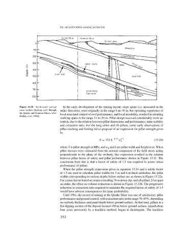
Figure 13.20 North–south vertical In the early development of the mining layout, stope spans (i.e. measured in the
cross section (looking east) through strike direction), were originally in the range 6 m–30 m, but operating experience of
the Quirke and Denison Mines (after
local structural control of roof performance, and local instability, resulted in adopting
Hedley et al., 1984).
working spans in the range 15 m–20 m. Pillar design received considerably more at-
tention, due to the relation between pillar dimensions and performance, mine stability
and extraction ratio. For the long strike and rib pillars, some early observations of
pillar crushing and fretting led to proposal of an expression for pillar strength given
by
S = 133 h −0.75 w 0.5 (13.24)
p
where S is pillar strength in MPa, and w p and h are pillar width and height in m. When
pillar stresses were estimated from the normal component of the field stress acting
perpendicular to the plane of the orebody, this expression resulted in the relation
between pillar factor of safety and pillar performance shown in Figure 13.21. The
conclusion from this is that a factor of safety of 1.5 was required to assure intact
performance of pillars.
When the pillar strength expression given in equation 13.24 and a safety factor
of 1.5 are used to calculate pillar widths for 3 m and 6 m thick orebodies, the pillar
widths corresponding to various depths below surface are as shown in Figure 13.22a.
For a mine layout based on stopes extending 76 m down-dip, and rib pillars 23 m apart
on strike, the effect on volume extraction is shown in Figure 13.22b. The progressive
reduction in extraction ratio required to maintain the required factor of safety of 1.5
would have adverse consequences for mine profitability.
Until 1981, the record of mining at the Quirke Mine was one of satisfactory pillar
performanceandgroundcontrol,withextractionratiointherange70–85%,depending
on orebody thickness and panel depth below ground surface. At that time, pillars in a
flat dipping section of the deposit located 450 m below ground surface, mined about
four years previously by a trackless method, began to disintegrate. The trackless
392