
Page 481 - Rock Mechanics For Underground Mining
P. 481
SUBLEVEL CAVING
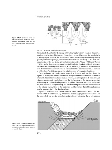
Figure 15.29 Increased scale of
sublevel caving at the Kiruna Mine,
Sweden, between (a) 1983, and (b)
1993 (after Marklund and Hustrulid,
1995).
15.4.3 Support and reinforcement
The methods described for designing sublevel caving layouts are based on the geome-
try of the gravity flow of broken ore. It must be recognised, however, that, particularly
as mining depths increase, the ‘honeycomb’ effect produced by the relatively closely
spaced production openings, can lead to stress-induced instability in the rock sur-
rounding the drifts and in the pillars between the drifts. Yenge (1980) and Tucker
(1981) describe the transverse fracturing of pillars in longitudinal sublevel caving op-
erations at the Pea Ridge iron ore mine, USA, where high horizontal in situ stresses
exist. Such occurrences may require re-orientation of the mining direction, an increase
in sublevel and/or drift spacing, or the reinforcement of production headings.
The distribution of elastic stress induced in layouts such as that shown in
Figure 15.26 may be readily determined using the numerical methods outlined in
Chapter 6. Strength/stress checks carried out using an appropriate rock mass strength
criterion, can then give an indication of the likely extent of the fracture zones that
will develop around the headings and in the pillars. However, numerical analysis of
the problem can be complicated by the relatively complex three-dimensional nature
of the mining layout, yield of the rock mass and by the fact that additional stresses
may be imposed during the drawing of ore.
Figure 15.30 illustrates a further cause of stress concentration around the pro-
duction levels in sublevel caving operations. As mining progresses downwards with
the removal of ore and the attendant caving of the waste rock, the in situ stresses
Figure 15.30 Schematic illustration
of the transverse horizontal stress con-
centration produced in the mining area
by a notch effect.
463