
Page 571 - Rock Mechanics For Underground Mining
P. 571
MONITORING SYSTEMS
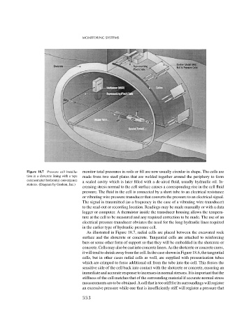
Figure 18.7 Pressure cell installa- monitor total pressures in soils or fill are now usually circular in shape. The cells are
tion in a shotcrete lining with a tape made from two steel plates that are welded together around the periphery to form
extensometer horizontal convergence
a sealed cavity which is later filled with a de-aired fluid, usually hydraulic oil. In-
stations. (Diagram by Geokon, Inc.)
creasing stress normal to the cell surface causes a corresponding rise in the cell fluid
pressure. The fluid in the cell is connected by a short tube to an electrical resistance
or vibrating wire pressure transducer that converts the pressure to an electrical signal.
The signal is transmitted (as a frequency in the case of a vibrating wire transducer)
to the read-out or recording location. Readings may be made manually or with a data
logger or computer. A thermistor inside the transducer housing allows the tempera-
ture at the cell to be measured and any required correction to be made. The use of an
electrical pressure transducer obviates the need for the long hydraulic lines required
in the earlier type of hydraulic pressure cell.
As illustrated in Figure 18.7, radial cells are placed between the excavated rock
surface and the shotcrete or concrete. Tangential cells are attached to reinforcing
bars or some other form of support so that they will be embedded in the shotcrete or
concrete. Cells may also be cast into concrete liners. As the shotcrete or concrete cures,
it will tend to shrink away from the cell. In the case shown in Figure 18.6, the tangential
cells, but in other cases radial cells as well, are supplied with pressurisation tubes
which are crimped to force additional oil from the tube into the cell. This forces the
sensitive side of the cell back into contact with the shotcrete or concrete, ensuring an
immediateandaccurateresponsetoincreasesinnormalstresses.Itisimportantthatthe
stiffness of the cell matches that of the surrounding material if accurate normal stress
measurementsaretobeobtained.Acellthatistoostiffforitssurroundingswillregister
an excessive pressure while one that is insufficiently stiff will register a pressure that
553