
Page 575 - Rock Mechanics For Underground Mining
P. 575
MONITORING SYSTEMS
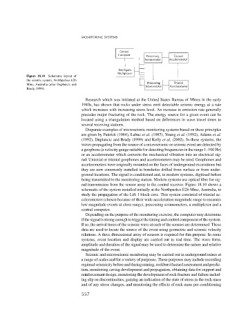
Figure 18.10 Schematic layout of
the seismic system, Northparkes E26
Mine, Australia (after Duplancic and
Brady, 1999).
Research which was initiated at the United States Bureau of Mines in the early
1940s, has shown that rocks under stress emit detectable seismic energy at a rate
which increases with increasing stress level. An increase in emission rate generally
precedes major fracturing of the rock. The energy source for a given event can be
located using a triangulation method based on differences in wave travel times to
several receiving stations.
Disparate examples of microseismic monitoring systems based on these principles
are given by Pattrick (1984), Labuc et al. (1987), Young et al. (1992), Adams et al.
(1992), Duplancic and Brady (1999) and Kelly et al. (2002). In these systems, the
waves propagating from the source of a microseismic or seismic event are detected by
a geophone (a velocity gauge suitable for detecting frequencies in the range 1–100 Hz)
or an accelerometer which converts the mechanical vibration into an electrical sig-
nal. Uniaxial or triaxial geophones and accelerometers may be used. Geophones and
accelerometers were originally mounted on the faces of underground excavations but
they are now commonly installed in boreholes drilled from surface or from under-
ground locations. The signal is conditioned and, in modern systems, digitised before
being transmitted to the monitoring station. Modern systems use optical fibre for sig-
nal transmission from the sensor array to the central receiver. Figure 18.10 shows a
schematic of the system installed initially at the Northparkes E26 Mine, Australia, to
study the propagation of the Lift 1 block cave. This system consisted of triaxial ac-
celerometers (chosen because of their wide acceleration magnitude range to measure
low magnitude events at close range), processing seismometers, a multiplexer and a
central computer.
Depending on the purpose of the monitoring exercise, the computer may determine
ifthesignalisstrongenoughtotriggerthetimingandcontrolcomponentofthesystem.
If so, the arrival times of the seismic wave at each of the sensors are determined. These
data are used to locate the source of the event using geometric and seismic velocity
relations. A three dimensional array of sensors is required for this purpose. In some
systems, event location and display are carried out in real time. The wave form,
amplitude and duration of the signal may be used to determine the nature and relative
magnitude of the event.
Seismic and microseismic monitoring may be carried out in underground mines at
a range of scales and for a variety of purposes. These purposes may include recording
regionalseismicitybeforeandduringmining,rockbursthazardassessmentandpredic-
tion, monitoring caving development and propagation, obtaining data for support and
reinforcement design, monitoring the development of rock fracture and failure includ-
ing slip on discontinuities, gaining an indication of the state of stress in the rock mass
and of any stress changes, and monitoring the effects of rock mass pre-conditioning
557