
Page 573 - Rock Mechanics For Underground Mining
P. 573
MONITORING SYSTEMS
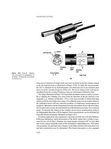
Figure 18.8 Uniaxial vibrating
wire stressmeter; (a) photograph, (b)
schematic. (Photograph and diagram
by Geokon, Inc.)
frequency of vibration of a high tensile steel wire stretched across the cylinder normal
to the pre-load direction as illustrated in Figure 18.8b. To make the measurements,
the wire is ‘plucked’ by an electromagnetic coil which also acts as an electronic pick
up to record the resonant frequency of the wire. The stress change in the rock may be
calculated from the recorded frequency using pre-determined calibration data.
The gauge illustrated in Figure 18.8 represents an improvement on earlier versions.
By re-aligning the vibrating wire away from the direction of the pre-load as it was
originally (e.g. Hawkes and Hooker, 1974), it has been possible to obtain both high
initial sensitivity and a large stress range. Given that the gauge acts as a rigid inclusion,
the calibration factor will vary with rock modulus. If temperature measurements are
required, a thermistor can be incorporated into the stressmeter. Even with all of these
factorstakenintoaccount,themainlimitationoftheinstrumentremains.Itisauniaxial
gauge. To measure the change in the complete stress tensor, measurements made in
six independent directions will be required. Such measurements can be facilitated by
using the biaxial stressmeter illustrated in Figure 18.9.
In mining application, this instrument is typically grouted into a 60 mm borehole.
Following installation, radial deformation of the thick-walled steel cylinder is mea-
◦
sured by two sets of three vibrating wire strain gauges oriented at 60 to each other
and closely spaced along the centre of the instrument’s longitudinal axis. From these
measurements, the principal stress changes in the plane normal to the instrument axis
and their orientations may be determined. The biaxial stressmeter is also equipped
555