
Page 217 - Root Cause Failure Analysis
P. 217
Control Valves 205
liner, a mechanically fastened resilient liner, an insert-type reinforced resilient liner,
or an integral metal seat with an O-ring inserted around the edge of the disk.
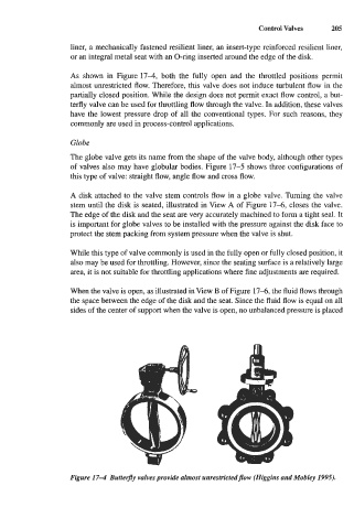
As shown in Figure 174, both the fully open and the throttled positions permit
almost unrestricted flow. Therefore, this valve does not induce turbulent flow in the
partially closed position. While the design does not permit exact flow control, a but-
terfly valve can be used for throttling flow through the valve. In addition, these valves
have the lowest pressure drop of all the conventional types. For such reasons, they
commonly are used in process-control applications.
Globe
The globe valve gets its name from the shape of the valve body, although other types
of valves also may have globular bodies. Figure 17-5 shows three configurations of
this type of valve: straight flow, angle flow and cross flow.
A disk attached to the valve stem controls flow in a globe valve. Turning the valve
stem until the disk is seated, illustrated in View A of Figure 17-6, closes the valve.
The edge of the disk and the seat are very accurately machined to form a tight seal. It
is important for globe valves to be installed with the pressure against the disk face to
protect the stem packing from system pressure when the valve is shut.
While this type of valve commonly is used in the fully open or fully closed position, it
also may be used for throttling. However, since the seating surface is a relatively large
area, it is not suitable for throttling applications where fine adjustments are required.
When the valve is open, as illustrated in View B of Figure 17-6, the fluid flows through
the space between the edge of the disk and the seat. Since the fluid flow is equal on all
sides of the center of support when the valve is open, no unbalanced pressure is placed
Figure 17-4 Buttefly valves provide almost unreshictedjlow (Higgins and Mobley 1995).