
Page 215 - Root Cause Failure Analysis
P. 215
Control Valves 203
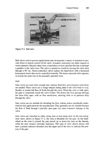
Figure 17-1 Ball valve.
Ball valves used in process applications may incorporate a variety of actuators to pro-
vide direct or remote control of the valve. Actuators commonly are either manual or
motor operated. Manual values have a handwheel or lever attached directly or through
a gearbox to the valve stem. The valve is opened or closed by moving the valve stem
through a 90" arc. Motor-controlled valves replace the handwheel with a fractional
horsepower motor that can be controlled remotely. The motor-operated valve operates
in exactly the same way as the manually operated valve.
Gate
Gate valves are used when straight-line, laminar fluid flow and minimum restrictions
are needed. These valves use a wedge-shaped sliding plate in the valve body to stop,
throttle, or permit full flow of fluids through the valve. When the valve is wide open,
the gate is completely inside the valve bonnet. This leaves the flow passage through
the valve fully open, with no flow restrictions, allowing little or no pressure drop
through the valve.
Gate valves are not suitable for throttling the flow volume unless specifically autho-
rized for this application by the manufacturer. They generally are not suitable because
the flow of fluid through a partially open gate can cause extensive damage to the
valve.
Gate valves are classified as either rising stem or non-rising stem. In the non-rising-
stem valve, shown in Figure 17-2, the stem is threaded into the gate. As the hand-
wheel on the stem is rotated, the gate travels up or down the stem on the threads,
while the stem remains vertically stationary. This type of valve almost always will
have a pointer indicator threaded onto the upper end of the stem to indicate the posi-
tion of the gate.