
Page 220 - Root Cause Failure Analysis
P. 220
208 Root Cause Failure Analysis
controlled valve will not position properly are mechanical wear or looseness between
the lever or handwheel and the disk, ball, or gate.
For remotely controlled valves, however, other variables have a direct impact on valve
travel. These variables depend on the type of actuator used. There are three major
types of actuators: pneumatic, hydraulic, and electronic.
Pneumatic actuators, including diaphragms, air motors, and cylinders, are suitable for
simple odoff valve applications. As long as there is enough air volume and pressure
to activate the actuator, the valve can be repositioned over its full length of travel.
However, when the air supply required to power the actuator is inadequate or the pro-
cess-system pressure is too great, the actuator’s ability to operate the valve properly is
severely reduced.
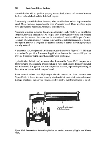
A pneumatic (Le., compressed-air driven) actuator is shown in Figure 17-7. This type
is not suited for precision flow-control applications, because the compressibility of air
prevents it from providing smooth, accurate valve positioning.
Hydraulic (Le., fluid-driven) actuators, also illustrated in Figure 17-7, can provide a
positive means of controlling process valves in most applications. Properly installed
and maintained, this type of actuator can provide accurate, repeatable positioning of
the control valve over its full range of travel.
Some control valves use high-torque electric motors as their actuator (see
Figure 17-8). If the motors are properly sized and their control circuits maintained,
this type of actuator can provide reliable, positive control over the full range of travel.
Figure 17-7 Pneumatic or hydraulic cylinders are used as actuators (Higgins and Mobley
1995).