
Page 172 - Satellite Communications, Fourth Edition
P. 172
152 Chapter Six
z
b
y
a
Perfectly conducting
infinite ground plane
x
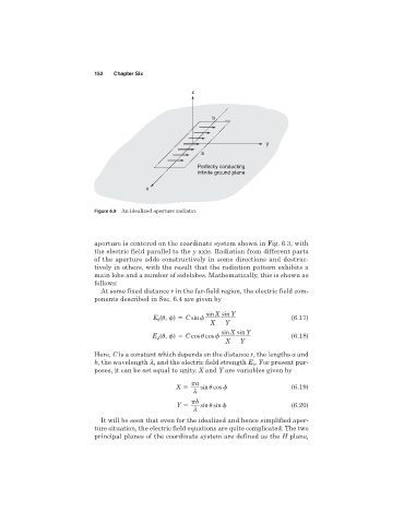
Figure 6.9 An idealized aperture radiator.
aperture is centered on the coordinate system shown in Fig. 6.3, with
the electric field parallel to the y axis. Radiation from different parts
of the aperture adds constructively in some directions and destruc-
tively in others, with the result that the radiation pattern exhibits a
main lobe and a number of sidelobes. Mathematically, this is shown as
follows:
At some fixed distance r in the far-field region, the electric field com-
ponents described in Sec. 6.4 are given by
sin X sin Y
E
(
, ) C sin (6.17)
X Y
sin X sin Y
E (
, ) C cos
cos (6.18)
X Y
Here, C is a constant which depends on the distance r, the lengths a and
b, the wavelength l, and the electric field strength E . For present pur-
0
poses, it can be set equal to unity. X and Y are variables given by
a
X sin
cos (6.19)
l
b
Y sin
sin (6.20)
l
It will be seen that even for the idealized and hence simplified aper-
ture situation, the electric field equations are quite complicated. The two
principal planes of the coordinate system are defined as the H plane,