
Page 174 - Satellite Communications, Fourth Edition
P. 174
154 Chapter Six
1
0.9
0.8
0.7
0.6
g E (θ) g H (θ) 0.5
0.4
0.3
0.2
0.1
0
0 10 20 30 40 50 60 70 80 90 100
θ
deg
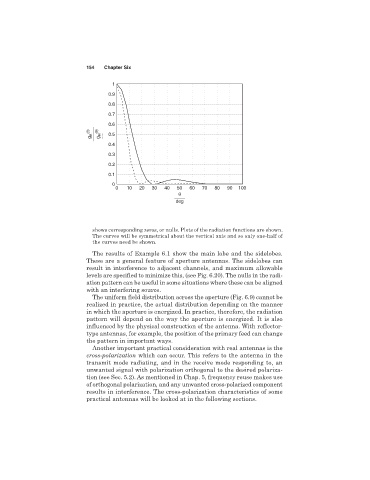
shows corresponding zeros, or nulls. Plots of the radiation functions are shown.
The curves will be symmetrical about the vertical axis and so only one-half of
the curves need be shown.
The results of Example 6.1 show the main lobe and the sidelobes.
These are a general feature of aperture antennas. The sidelobes can
result in interference to adjacent channels, and maximum allowable
levels are specified to minimize this, (see Fig. 6.20). The nulls in the radi-
ation pattern can be useful in some situations where these can be aligned
with an interfering source.
The uniform field distribution across the aperture (Fig. 6.9) cannot be
realized in practice, the actual distribution depending on the manner
in which the aperture is energized. In practice, therefore, the radiation
pattern will depend on the way the aperture is energized. It is also
influenced by the physical construction of the antenna. With reflector-
type antennas, for example, the position of the primary feed can change
the pattern in important ways.
Another important practical consideration with real antennas is the
cross-polarization which can occur. This refers to the antenna in the
transmit mode radiating, and in the receive mode responding to, an
unwanted signal with polarization orthogonal to the desired polariza-
tion (see Sec. 5.2). As mentioned in Chap. 5, frequency reuse makes use
of orthogonal polarization, and any unwanted cross-polarized component
results in interference. The cross-polarization characteristics of some
practical antennas will be looked at in the following sections.