
Page 175 - Satellite Communications, Fourth Edition
P. 175
Antennas 155
The aperture shown in Fig. 6.9 is linearly polarized, the E vector
being directed along the y axis. At some arbitrary point in the far-field
region, the wave will remain linearly polarized, the magnitude E being
given by Eq. (6.1). It is only necessary for the receiving antenna to be
oriented so that E induces maximum signal, with no component orthog-
onal to E so that cross-polarization is absent. Care must be taken, how-
ever, in how cross-polarization is defined. The linearly polarized field E
can be resolved into two vectors, one parallel to the plane containing the
aperture vector E , referred to as the copolar component, and a second
0
component orthogonal to this, referred to as the cross-polarized compo-
nent. The way in which these components are used in antenna meas-
urements is detailed in Chang (1989) and Rudge et al. (1982).
6.12 Horn Antennas
The horn antenna is an example of an aperture antenna that provides
a smooth transition from a waveguide to a larger aperture that couples
more effectively into space. Horn antennas are used directly as radia-
tors aboard satellites to illuminate comparatively large areas of the
earth, and they are also widely used as primary feeds for reflector type
antennas both in transmitting and receiving modes. The three most
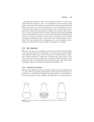
commonly used types of horns are illustrated in Fig. 6.10.
6.12.1 Conical horn antennas
The smooth-walled conical antenna shown in Fig. 6.10 is the simplest horn
structure. The term smooth-walled refers to the inside wall. The horn may
be fed from a rectangular waveguide, but this requires a rectangular-to-
circular transition at the junction. Feeding from a circular guide is
Figure 6.10 Horn antennas: (a) smooth-walled conical, (b) corrugated, and
(c) pyramidal.